Cutting tooth for earth working equipment

A technology of working tools and cutting teeth, which is applied in the field of cutting teeth, can solve problems such as premature wear and increased cost of spare parts, and achieve reliable cutting, high cutting speed, and good cutting process.

Active Publication Date: 2007-05-02
BAUER MASCH GMBH
View PDF2 Cites 9 Cited by
  • Summary
  • Abstract
  • Description
  • Claims
  • Application Information

AI Technical Summary

Problems solved by technology

When replacing cutters, there is also the risk of installing a cutter not suitable for the given inclination angle, which can lead to premature wear and increase the cost of spare parts

Method used


Image

  • Cutting tooth for earth working equipment
  • Cutting tooth for earth working equipment
  • Cutting tooth for earth working equipment

Examples


Embodiment Construction

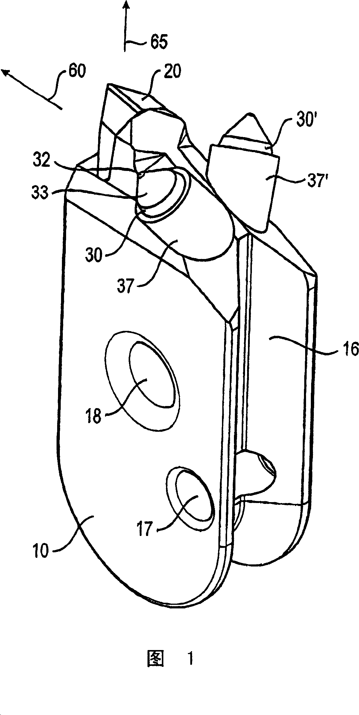
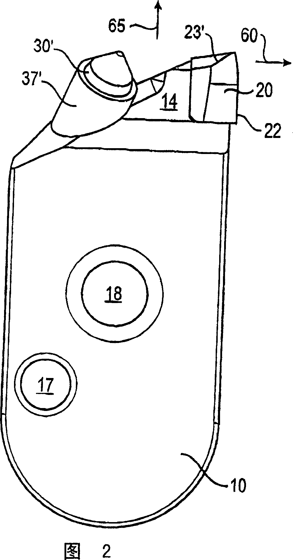
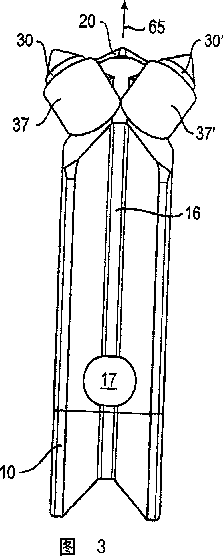
[0044] 1 to 4 show a first embodiment of a cutting tooth according to the invention. On the underside of the cutting tooth, the cutting tooth has a tooth root 10 which is received in a cutting tooth holder. In the side view shown in FIG. 2 , the dedendum 10 is U-shaped with two parallel front edges and a rounded bottom. A longitudinal groove 16 with a substantially V-shaped cross-section is provided on both front faces of the cutting tooth, which is approximately radial when placed on the cutting wheel, and in the base region of the tooth root 10 . The longitudinal groove 16 forms part of a positive connection by which the cutting tooth is releasably secured in a not shown cutting tooth holder.

[0045] The dedendum 10 also has a crosshole 17 which intersects the longitudinal groove 16 and also the solid part of the adjacent dedendum 10 . Intersecting holes 17 receive shear pins to secure the cutter 10 in the holder. A further cross hole 18 is provided on the tooth root 10,...


PUM


Abstract

Cutting tooth has foot to sit in a seat on the ground treatment appliance and at least one main cutting part is located on the cutting foot on the head side to treat the ground material. To enlarge the treatment area of the main cutting piece situated on the foot, a further post cutting piece is provided. It has a different cutting design compared to the main cutting piece. The post cutting piece has a pin blade. The main cutting piece has at least one wedge-shaped blade.

Description

technical field [0001] The present invention relates to a cutting tooth for a ground working tool, in particular for a cutting wheel of a trench wall cutting machine, according to the preamble of technical solution 1 . Such a cutting tooth has a root portion or root received in a holder of a ground working tool and at least one main cutting element working the soil on the root tip. Background technique [0002] Such cutting teeth are known, for example, from DE 297 20 261 U1 and DE 87 15 141 U1 and are used in trench wall cutters for underground work in order to produce trench walls. Cutting teeth are particularly useful in wheel cutters, wherein the cutting teeth are located on the peripheral surface of the cutting wheel. To create the trench, the cutting wheel is rotated and lowered into the ground. The cutting teeth break up and loosen the soil against the cutting wheel, so that with the aid of the pump, for example, the soil can be sucked up and / or the soil can be proc...

Claims


Application Information

Patent Timeline
Patent Type & Authority Applications(China)
IPC IPC(8): E02F9/28E02F5/08E02F5/14
CPCE02F9/2858E02F9/2866
Inventor E·斯托特泽
Owner BAUER MASCH GMBH
Why Eureka
Try Eureka