
Failure diagnosis system, failure diagnosis device and failure diagnosis program

a failure diagnosis and failure technology, applied in the field of failure diagnosis systems, failure diagnosis devices, failure diagnosis programs, etc., can solve the problem of rare cases, achieve high-quality diagnosis, improve the probability of maintenance workers carrying out accurate treatment, and improve the service level

Inactive Publication Date: 2012-11-15
HITACHI LTD
View PDF3 Cites 40 Cited by
  • Summary
  • Abstract
  • Description
  • Claims
  • Application Information

AI Technical Summary

Benefits of technology

[0015]The effects obtained by typical embodiments of the invention disclosed in the present application will be briefly described below.
[0016]That is, in accordance with the effects obtained by the typical embodiments, maintenance case information including data ambiguity and a partially deficient portion can be systematically accumulated by effectively utilizing parts delivery information and sensor information derived from each equipment, so that it is possible to create a detailed and highly accurate diagnosis rule. By this means, the probability of the maintenance worker carrying out an accurate treatment is improved, and the improvement of the service level and the reduction of the working cost and storage cost can be achieved as a result of the improvement of the working speed.BRIEF DESCRIPTIONS OF THE DRAWINGS
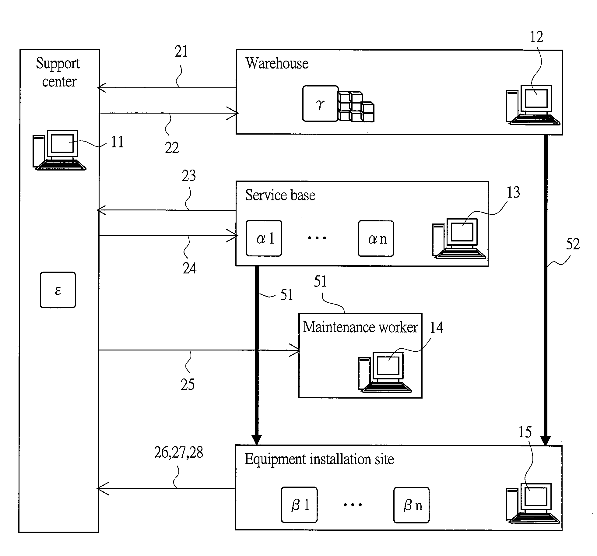
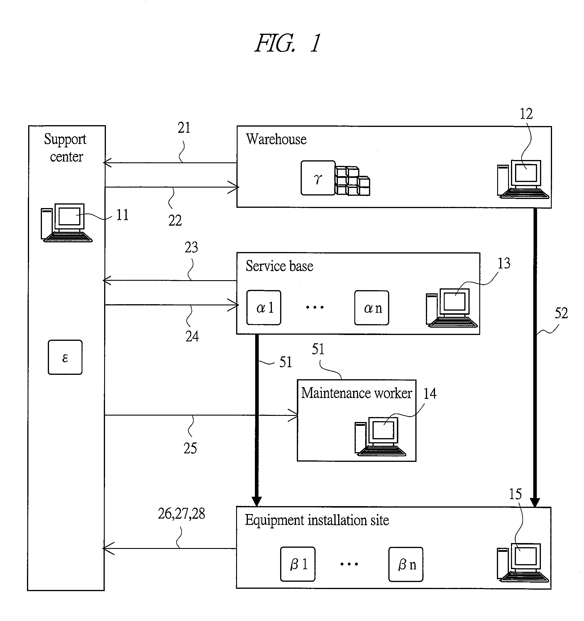
[0017]FIG. 1 is an explanatory drawing that shows a maintenance service model that is supposed to be a subject to which a failure diagnosis system according to one embodiment of the present invention is applied;
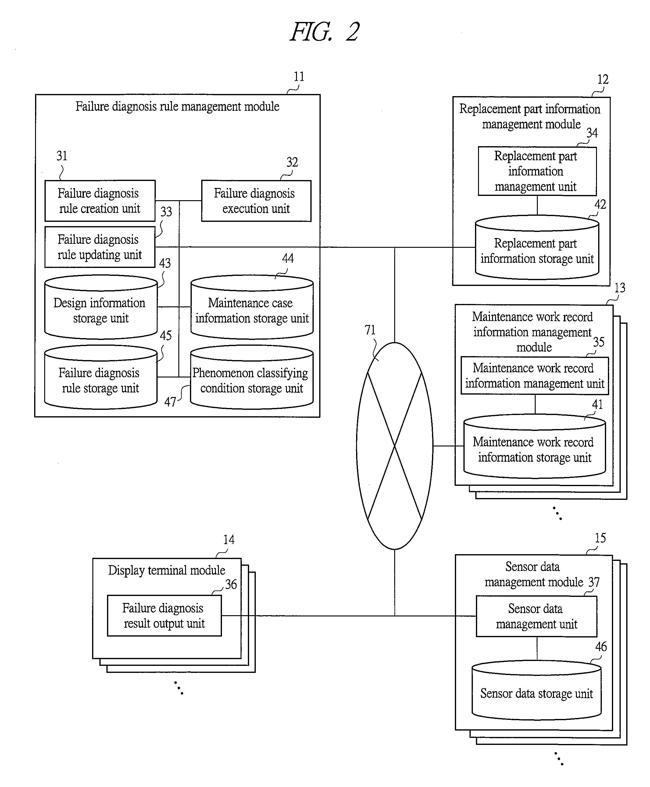
[0018]FIG. 2 is a block diagram that shows a configuration of the failure diagnosis system according to the embodiment of the present invention;
[0019]FIG. 3 is a block diagram that shows a configuration of an information terminal of each module of the failure diagnosis system according to the embodiment of the present invention;
[0020]FIG. 4A is a drawing that shows a holding data structure held by a calculation information storage unit of the failure diagnosis system according to the embodiment of the present invention;

Problems solved by technology

However, it is rare to find such a case where the maintenance case information is accumulated in a manner that satisfies the precondition.

Method used


Image

  • Failure diagnosis system, failure diagnosis device and failure diagnosis program
  • Failure diagnosis system, failure diagnosis device and failure diagnosis program
  • Failure diagnosis system, failure diagnosis device and failure diagnosis program

Examples


Embodiment Construction

[0035]Hereinafter, embodiments of the present invention will be described in detail with reference to the accompanying drawings. Note that components having the same function are denoted by the same reference symbols throughout the drawings for describing the embodiments, and the repetitive description thereof will be omitted.

[0036]

[0037]A maintenance service model that is supposed to be a subject to which a failure diagnosis system according to one embodiment of the present invention is applied will be described with reference to FIG. 1. FIG. 1 is an explanatory drawing that shows the maintenance service model that is supposed to be a subject to which the failure diagnosis system according to one embodiment of the present invention is applied.

[0038]Here, manufacturing equipment to which the failure diagnosis system of the present embodiment is applied includes power generation facilities, plants, construction equipment, aircrafts, automobiles, elevators, and others. Moreover, inspe...


PUM


Abstract

In the failure diagnosis system of the present invention, the maintenance case information including data ambiguity and a partially deficient portion is utilized even in the case where maintenance case information having a high similarity is not sufficiently provided. The failure diagnosis system is provided with: a failure diagnosis rule creation unit 31 which, by utilizing maintenance case information accumulated in the past, creates a failure diagnosis rule used for listing up candidates of maintenance parts required for recovering the equipment from a failure phenomenon; a failure diagnosis execution unit 32 which, upon occurrence of a failure, outputs the candidates of maintenance parts required for recovering from the failure phenomenon to a maintenance work assist terminal with reference to the failure diagnosis rule; and a failure diagnosis rule updating unit 33 for updating the failure diagnosis rule, and the failure diagnosis rule creation unit 31 has a factor-information link creation unit, which creates links among pieces of factor information composed of pieces of information relating to the failure phenomenon, information relating to the subject component, and information relating to the corresponding treatment in the maintenance case information accumulated in the past.

Description

TECHNICAL FIELD[0001]The present invention relates to a failure diagnosis system, a failure diagnosis device, and a failure diagnosis program for assisting a maintenance work for manufacturing equipment and inspection equipment.BACKGROUND ART[0002]In order to maintain the performance of manufacturing equipment and inspection equipment for a long period of time, it is necessary to appropriately carry out a maintenance work such as parts replacement regularly or upon occurrence of a failure.[0003]Moreover, in the type of service that ensures a production ratio and quality in a predetermined level or more under a maintenance contract, the improvement of service level achieved by carrying out a failure diagnosis with high accuracy and good efficiency upon occurrence of a failure to reduce the down time for a required maintenance work such as parts replacement is the key to the improvement of a competitive force for increasing the amount of orders and is simultaneously connected directly...

Claims


Application Information

Patent Timeline
Patent Type & Authority Applications(United States)
IPC IPC(8): G06Q10/00G06Q50/00G06Q50/10
CPCG06Q10/00
Inventor MAGARA, HIROYUKIMAEDA, SHUNJISHIBUYA, HISAE
Owner HITACHI LTD
Learn More