Supercharge Your Innovation With Domain-Expert AI Agents!

Method for forming end heads of parts in beam type

A forming method and beam technology, applied in the forming field of stamping parts, can solve the problems of complex processing technology, complex mold structure, stress concentration, etc., and achieve the effect of simplifying process steps, reducing process difficulty, and eliminating stress concentration.

Inactive Publication Date: 2007-05-09
BYD CO LTD
View PDF0 Cites 0 Cited by
  • Summary
  • Abstract
  • Description
  • Claims
  • Application Information

AI Technical Summary

Problems solved by technology

[0004] However, this method of opening a process gap not only makes the structure of the mold very complicated, but also requires the design of multiple sets of molds, which increases the manufacturing cost, complicates the processing technology, and reduces the production efficiency.
At the same time, because the process gap on the part will affect the overall strength and rigidity of the part, and if there is even a small crack at the gap, it will also form stress concentration, so it will have a negative impact on the safety of the entire part and even the vehicle as a whole. Hidden danger

Method used


Image

  • Method for forming end heads of parts in beam type
  • Method for forming end heads of parts in beam type
  • Method for forming end heads of parts in beam type

Examples


Embodiment Construction

[0013] The present invention will be described in detail below in conjunction with the accompanying drawings.

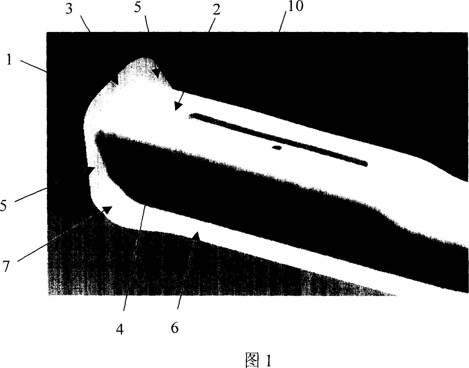
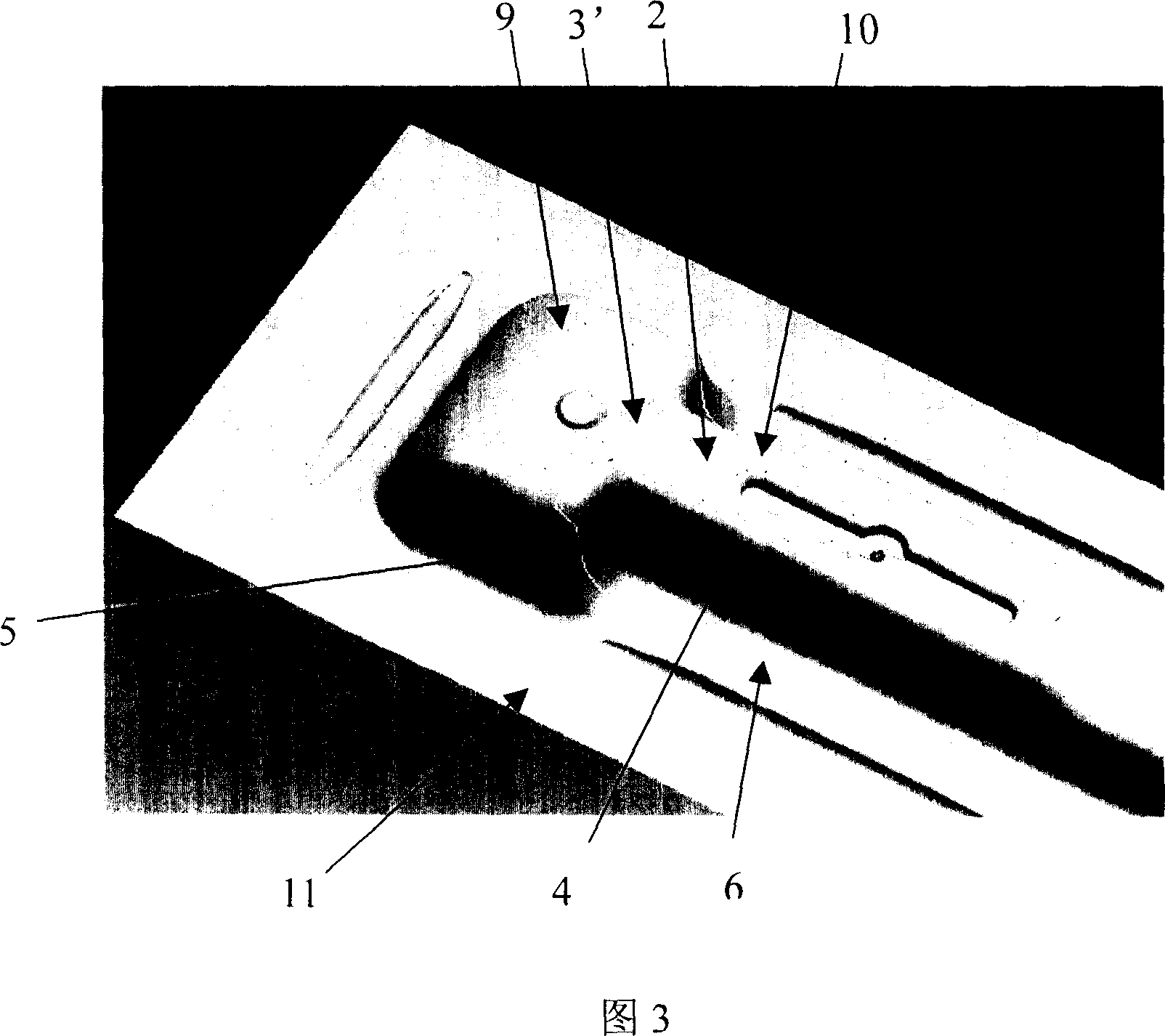
[0014] The method for forming the end of a beam-like part provided by the present invention includes drawing the workpiece into the shape of a beam, wherein the end of the drawn workpiece is connected to the two side surfaces 4 of the beam main body 10 and connected to the side surface 4. The side flanges 5 that are not on the same plane and the upper flange 3' connected to the upper surface 2 of the beam main body 10; then trim the workpiece; and finally flang the upper flange 3'.

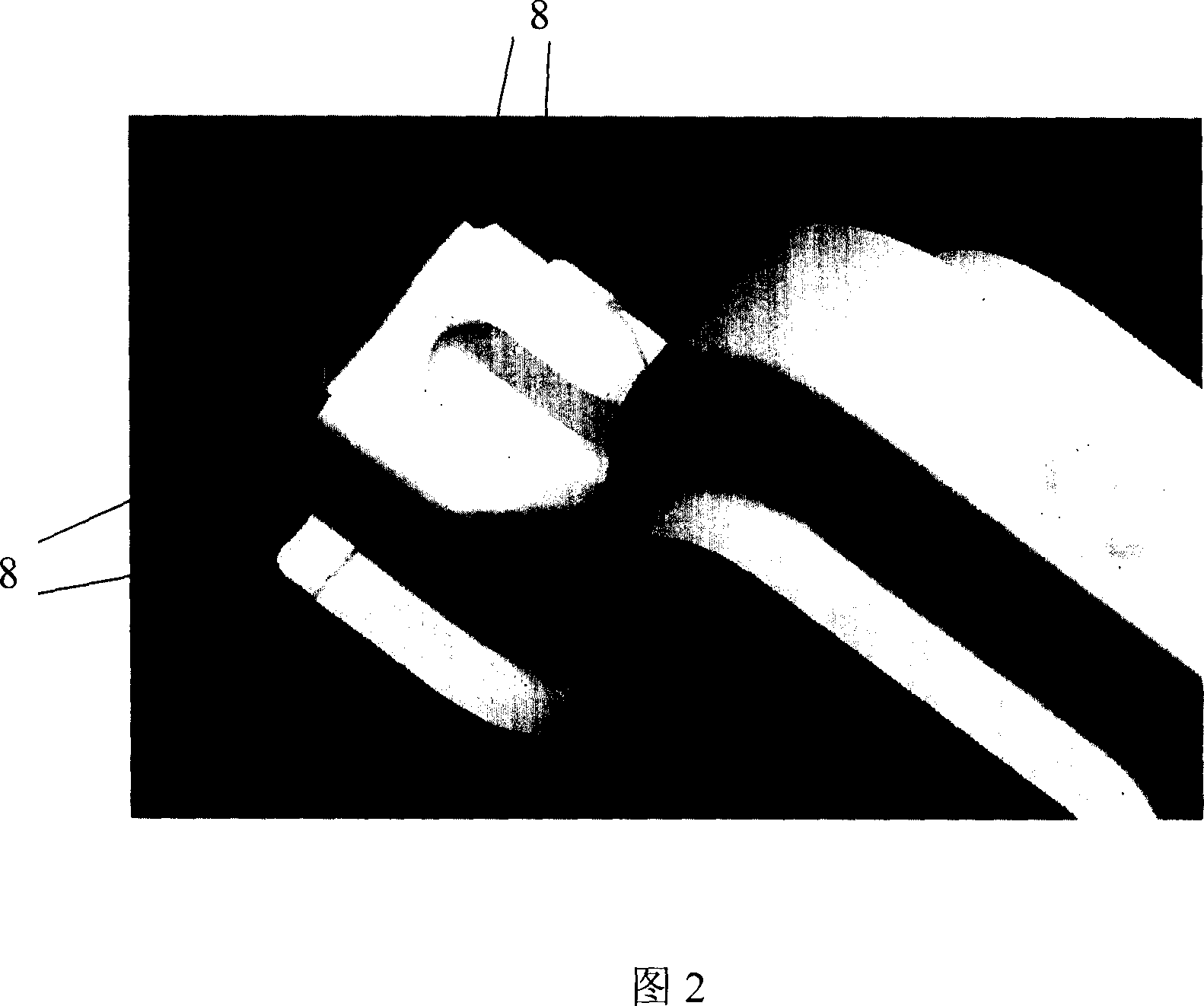
[0015] Preferably, the end of the article drawn into the shape of a beam includes a box-shaped portion 9 including sides respectively connected to the two side surfaces 4 of the beam body 10 and not in the same plane as the side surfaces 4 The flange side 5 and the upper flange side 3 ′ connected to the upper surface 2 of the beam main body 10 .

[0016] Preferably, the side flange 5 an...


PUM


Abstract

A method for shaping the terminal end of transverse beam includes such steps as die drawing to make the terminal end of a beam have two lateral flanges and one upper flange, strimming, and cupring said upper flange.

Description

technical field [0001] The invention relates to a forming method of stamping parts, more specifically, to a forming method of ends of beam parts. Background technique [0002] In recent years, the stamping process has been widely used in the automobile manufacturing industry. Many covering parts and interior panels in the vehicle are stamped by dies. Wherein, however, as shown in FIG. 1 , the end portions of some beam parts in the vehicle need to form a flange 1, wherein the flange 1 includes an upper flange 3 connected to the upper surface 2 of the beam main body 10 and respectively connected to The two side flange sides 5 connected by the two side surfaces 4 of the beam main body 10 form a certain angle between the upper flange side 3 and the upper surface 2 and between the side flange side 5 and the side surface 4 respectively, and from the side The portion 7 where the flange side 5 transitions to the outer edge 6 along the length direction of the beam main body 10 requi...

Claims


Application Information

Patent Timeline
Patent Type & Authority Applications(China)
IPC IPC(8): B21D35/00
Inventor 苏昆荣李淑英
Owner BYD CO LTD
Features
  • R&D
  • Intellectual Property
  • Life Sciences
  • Materials
  • Tech Scout
  • Unparalleled Data Quality
  • Higher Quality Content
  • 60% Fewer Hallucinations
Learn More