Liquid trap device for gas

一种捕捉装置、气体的技术,应用在气体用液体捕捉装置领域,能够解决液体捕捉性能低、液体捕捉性能降低、堵塞网眼等问题,达到提高液体捕捉性能、防止局部饱和、延长耐用时间的效果

Inactive Publication Date: 2007-05-16
KEIHIN CORP
View PDF1 Cites 2 Cited by
  • Summary
  • Abstract
  • Description
  • Claims
  • Application Information

AI Technical Summary

Problems solved by technology

[0004] Conventionally, in this type of liquid capture device for gas, since the opening provided on the upper end wall of the liquid filter opens in the upper part of the filter element, the opening is relatively close to the gas outlet, so the gas flows into the filter element from the opening. Most of the gas tends to pass through the upper part of the filter element, so the upper part of the filter element is in a partially saturated state where the mesh is blocked by the liquid captured from the gas, so the liquid capture performance of the upper part of the filter element is extremely low
In addition, when liquid seeps out from a part of the filter element in a saturated state, the liquid advances to the gas outlet along with the flow of gas passing through the filter element, and then mixes with gas again, so that the liquid capture performance is lowered.

Method used


Image

  • Liquid trap device for gas
  • Liquid trap device for gas
  • Liquid trap device for gas

Examples


Embodiment Construction

[0028] Embodiments of the present invention will be described below based on preferred embodiments of the present invention shown in the accompanying drawings.

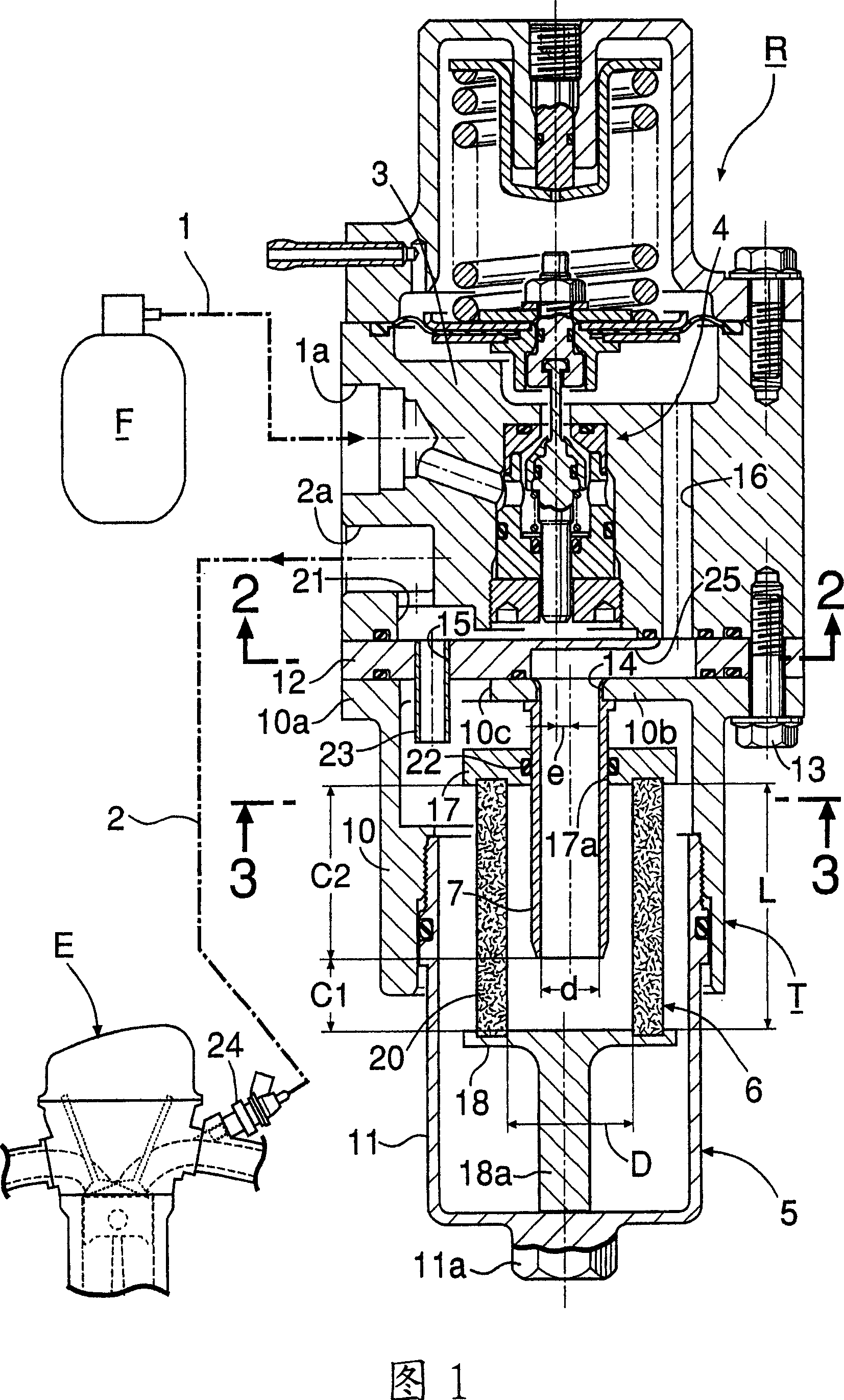
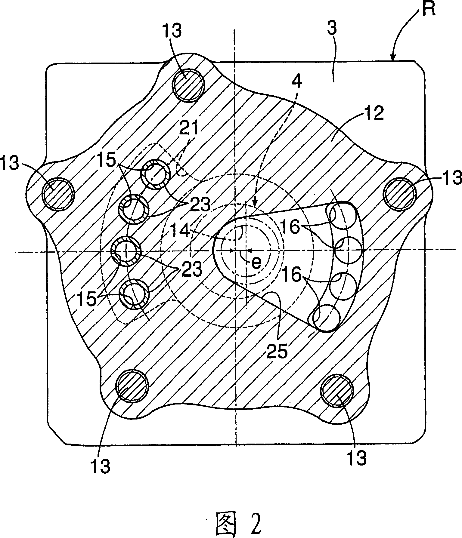
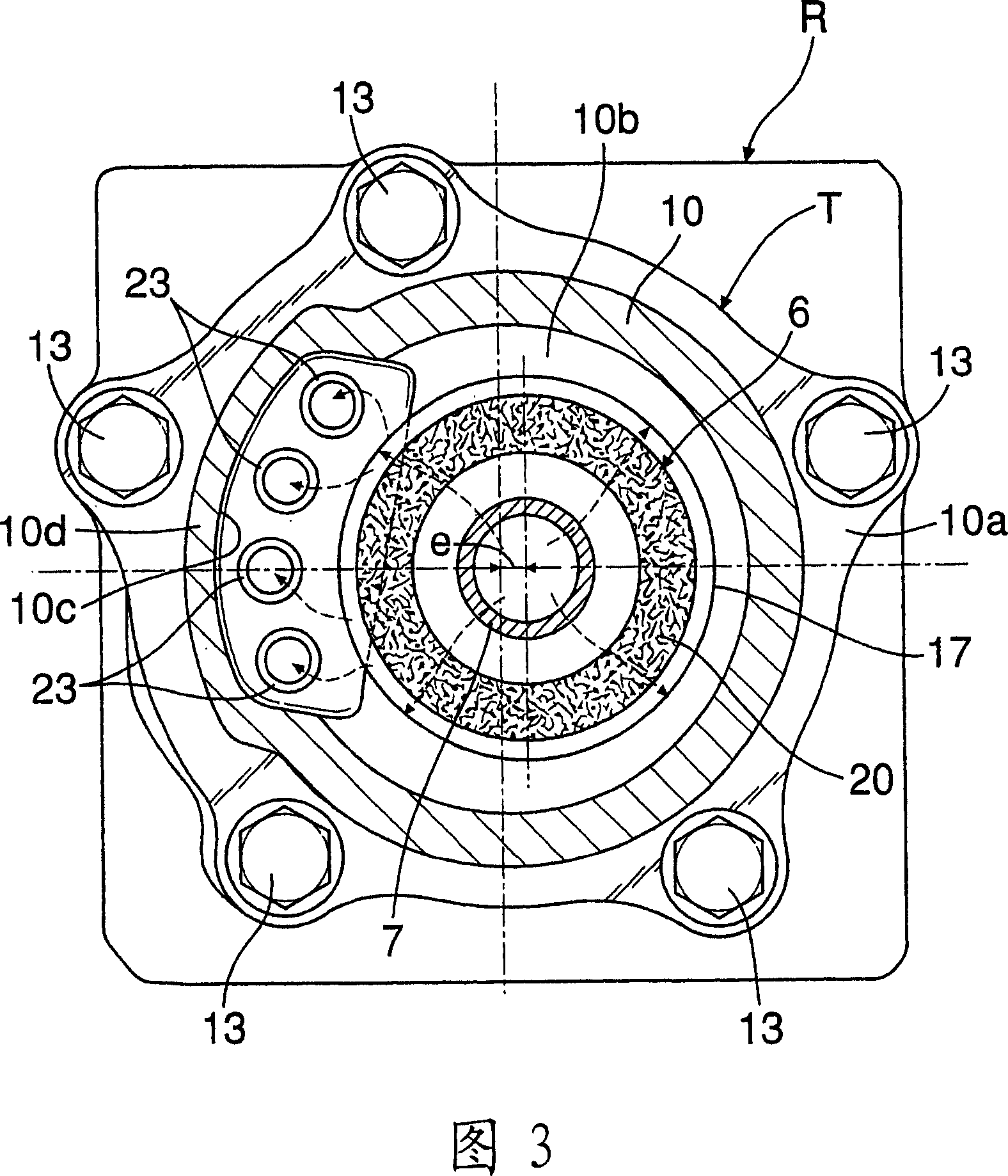
[0029] Fig. 1 is a longitudinal sectional view of a pressure regulator integrally provided with a gas-liquid capturing device according to an embodiment of the present invention, Fig. 2 is a sectional view along line 2-2 in Fig. 1 , and Fig. 3 is a sectional view along line 2 in Fig. 1 3-3 line sectional view, Fig. 4 is a sectional view of four kinds of gas liquid capture devices used as capture performance test samples, and Fig. 5 is a table showing the parameters and capture performance test results of the above four kinds of gas liquid capture devices , FIG. 6 is a graph showing the capture performance test results of the above-mentioned four kinds of gas liquid capture devices.

[0030] First, in FIG. 1, natural gas is compressed and stored in a fuel tank F as a gaseous fuel. When using the high-pressure gas fuel...


PUM


Abstract

A liquid trap device for gas includes a trap housing (5) and a liquid filter (6) disposed in the trap housing (5). The liquid filter (6) includes an upper end wall (17) having an opening (17a) communicating with a gas inlet (14), a lower end wall (18) and a cylindrical filter element (20) providing a connection between the upper end wall (17) and the lower end wall (18). An inflow guide tube (7) is disposed in the filter element (20), the inflow guide tube (7) having a uniform path area and extending from the opening (17a) to the lower end wall (18) so as to guide gas flowing into the gas inlet (14) into the filter element (20). A distance (C1) between a lower end of the inflow guide tube (7) and the lower end wall (18) is set at (20) mm or less. Thus, the liquid trap device for gas has a high performance for trapping liquid.

Description

technical field [0001] The present invention relates to an improvement of a liquid capture device for gas. The liquid capture device for gas is composed of a capture housing and a liquid filter. The capture housing has a top wall provided with a gas inlet and a gas outlet. The liquid filter The filter is arranged in the above-mentioned catcher housing, and includes a cylindrical filter element whose interior communicates with the above-mentioned gas inlet, and the above-mentioned gas outlet is on the outside of the liquid filter and opens inside the above-mentioned catcher housing. When the gas flowing from the inlet toward the gas outlet passes through the filter element, the liquid contained in the gas is captured by the filter element. Background technique [0002] For example, in an automobile having an engine fueled by natural gas, a fuel tank containing compressed natural gas is installed, and high-pressure gas fuel derived from the fuel tank is decompressed to a prede...

Claims


Application Information

Patent Timeline
Patent Type & Authority Applications(China)
IPC IPC(8): B01D46/24F04B39/16F02M37/22
CPCB01D46/2411B01D45/04B01D46/003B01D46/4272
Inventor 中岛要治山本博晓吉田崇后藤博之
Owner KEIHIN CORP
Why Eureka
Try Eureka