A high-voltage high-power cage motor rotor slot

A motor rotor, high-power technology, applied in the direction of electrical components, electromechanical devices, electric components, etc., can solve the problems of serious squeeze effect on the upper layer of the rotor guide bar, can not improve the local heating problem, affect the safe operation of the motor, etc., and achieve obvious energy saving effect, increase production cost, and improve operating efficiency

Active Publication Date: 2020-11-20
NORTH CHINA ELECTRIC POWER UNIV (BAODING)
View PDF12 Cites 0 Cited by
  • Summary
  • Abstract
  • Description
  • Claims
  • Application Information

AI Technical Summary

Problems solved by technology

All these will lead to severe heating of the rotor during the starting process, which may easily lead to failure
For some applications that require frequent starting, it is more likely to cause the motor guide bar to fuse and cause the motor to be damaged.
[0004] 2) During steady-state operation, due to the slotting of the stator and rotor and the arrangement of the windings, there are harmonic components in the air-gap magnetic field, which is especially serious during frequency conversion power supply. The air-gap magnetic field cuts the rotor and generates induced potential and induced current in the rotor. The relative movement of the magnetic field to the rotor will generate high-frequency harmonics in the rotor, which leads to a serious squeeze effect on the upper layer of the rotor guide bar during steady-state operation, and local heating is obvious, which affects the safe operation of the motor
[0006] The above improved design is only aimed at the improvement of a certain aspect of performance, such as the optimized design of the low harmonic stator winding type and slot shape, which can effectively reduce the influence of harmonic components on loss and local heating, but cannot improve the large current during the starting process. The local heating problem caused by the problem; choosing the appropriate slot fit can improve the harmonic component of the stator and rotor magnetic potential, but the harmonic current and additional loss generated by different harmonic components in the rotor guide bar have not been fundamentally eliminated
Therefore, the above measures have not simultaneously taken into account and solved the local overheating problem caused by the high current during the starting process of the high-voltage and high-power squirrel-cage asynchronous motor and the additional loss caused by the harmonic magnetic field during normal steady-state operation.

Method used


Image

  • A high-voltage high-power cage motor rotor slot
  • A high-voltage high-power cage motor rotor slot
  • A high-voltage high-power cage motor rotor slot

Examples


Embodiment 1

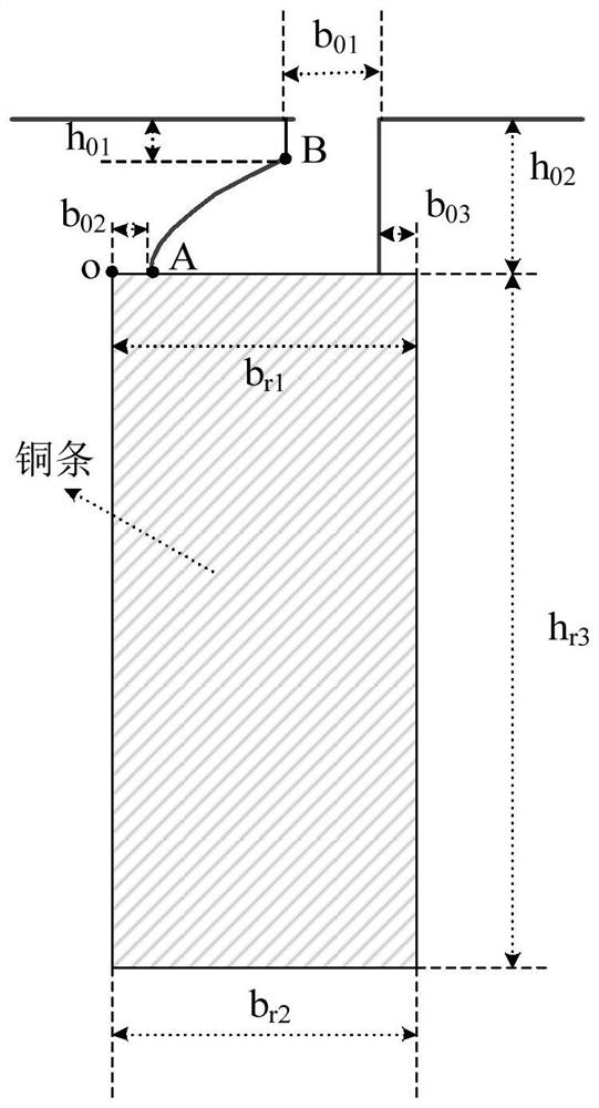
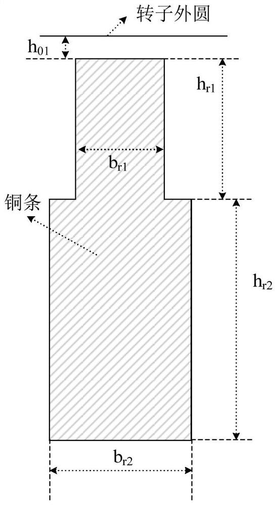
[0038] Taking the 900kW squirrel-cage asynchronous motor as an example, the original rotor groove diagram is shown in figure 2 , see the rotor groove type of this patent figure 1 According to the method provided by the patent of the present invention, the specific dimensions of the new rotor groove are determined as follows: b01=3.5mm; h01=2.2mm; h02=6.5mm; b02=b03=2mm; br1=11mm; br2=9mm; hr3=42mm . Draw a hyperbola with O(0,0) as coordinates Starting point A(2,0) and ending point B(5.5,4.3).

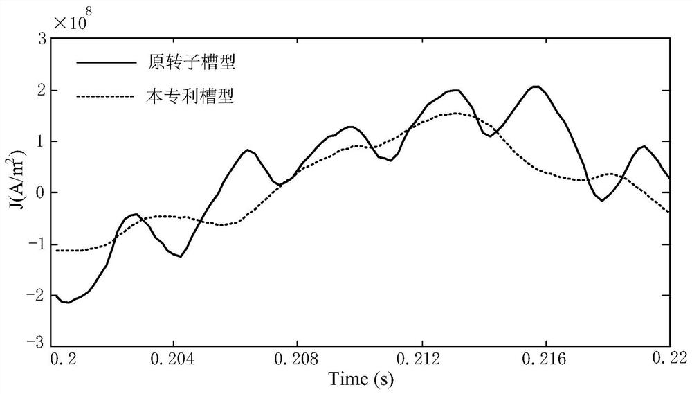
[0039] image 3 It is a comparison diagram of the current density waveform on the upper layer of a guide bar in the initial state of starting for the 900kW squirrel-cage asynchronous motor using the original rotor slot type and the new rotor slot type proposed in the present invention. It can be seen that the original rotor slot type The current density waveform of the starting rotor of the motor has a large harmonic content within a working cycle. According to Fourier analysis, t...

Embodiment 2

[0053] Taking the 1600kW squirrel-cage asynchronous motor as an example, the original rotor groove diagram is shown in Figure 6 , see the rotor groove type of this patent figure 1 According to the method provided by the patent of the present invention, the specific dimensions of the new rotor groove are determined as follows: b01=2mm; h01=2.2mm; h02=6.5mm; b02=b03=2mm; br1=8mm; br2=10.5mm; hr3=38mm ;Using O(0,0) as coordinates, draw a hyperbola Starting point A(2,0) and ending point B(4,4.3).

[0054] Figure 7 It is a comparison diagram of the current density waveform on the upper layer of a guide bar in the initial state of starting for the 1600kW squirrel-cage asynchronous motor using the original rotor slot type and the new rotor slot type proposed in the present invention. It can be seen that the original rotor slot type The current density waveform of the starting rotor of the motor has a large harmonic content within a working cycle. According to Fourier analysis, ...


PUM


Abstract

The invention belongs to the technical field of motor design and manufacturing, and particularly relates to a high-voltage high-power cage-type motor rotor slot, which comprises a rotor slot conducting bar part for inserting a rotor conducting bar, a slot opening, and an area with a cambered surface on one side between the rotor slot conducting bar part and the slot opening, the bottom edge of thearea is the central section of the upper edge of the rotor slot, one side of the area is connected with the lower edge of one side of the slot opening through a cambered surface, and the other side of the area is aligned with the other side of the slot opening. The vertical section of the cambered surface is a part of a hyperbolic curve in a first quadrant or a second quadrant in a rectangular coordinate system. The protruding direction of the hyperbolic curve in the first quadrant or the second quadrant in the rectangular plane coordinate system is consistent with the rotating direction of the motor rotor. According to the invention, high loss of the rotor generated by large current in starting of the high-voltage high-power motor and high-frequency additional loss generated by a harmonic magnetic field in steady-state operation are reduced, the problems of local overheating of the rotor slot opening and easy breakage of the rotor are fundamentally solved, and safe and reliable operation of the motor in actual production is further ensured.

Description

technical field [0001] The invention belongs to the technical field of motor design and manufacture, and in particular relates to a rotor slot of a high-voltage and high-power cage-type motor. Background technique [0002] In engineering practice, during start-up and operation of high-voltage and high-power squirrel-cage asynchronous motors that drive fluid loads, the rotor guide bars are prone to melting due to local overheating of the rotor slot, resulting in insulation damage between the guide bars and the iron core, and further development It becomes the failure of the rotor and end ring to deform or even break. The reasons for this phenomenon are mainly the following two points: [0003] 1) During the starting process, the rotor and load moment of inertia of the high-voltage high-power motor is large, and the direct starting has the characteristics of large starting current and long starting time. At the same time, the current frequency in the rotor bar is changing and ...

Claims


Application Information

Patent Timeline
Patent Type & Authority Patents(China)
IPC IPC(8): H02K1/26H02K1/28
CPCH02K1/265H02K1/28H02K2213/03
Inventor 赵海森储呈阳詹阳许国瑞康锦萍杨亚秋刘晓芳
Owner NORTH CHINA ELECTRIC POWER UNIV (BAODING)
Why Eureka
Try Eureka