
Holographic storage system with multiple reference beams

a reference beam and holographic storage technology, applied in the field of apparatus for reading from and/or writing to holographic storage media, can solve the problem of interference pattern in the overlap region of the reference beam overlap

Inactive Publication Date: 2012-05-01
THOMSON LICENSING SA
View PDF3 Cites 0 Cited by
  • Summary
  • Abstract
  • Description
  • Claims
  • Application Information

AI Technical Summary

Benefits of technology

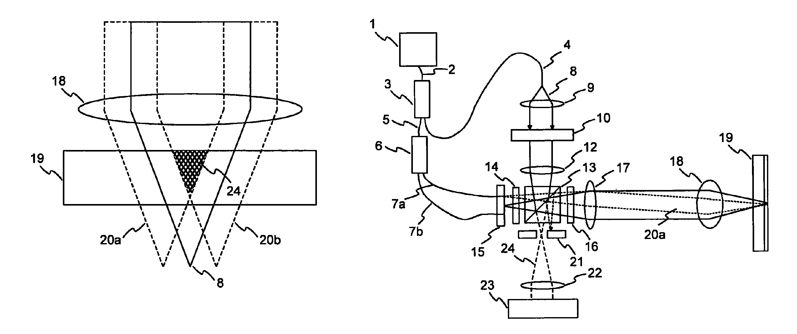
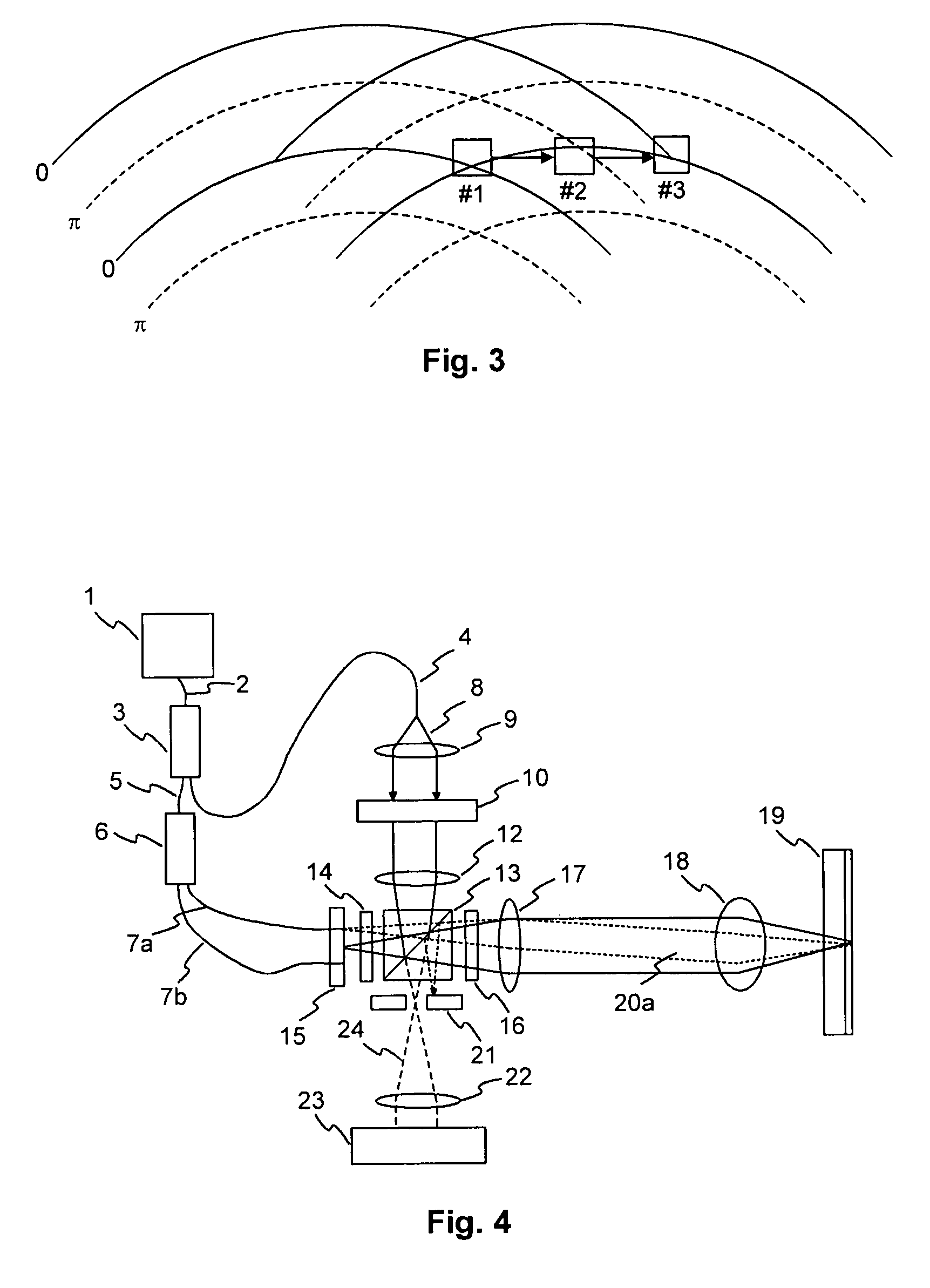
[0011]For writing a hologram the reference beams need to be coherent with the object beam. Otherwise no interference pattern is produced, which is the basis of holographic storage. In the prior art solutions using multiple reference beams, the multiple reference beams are generated in such way that they are mutually coherent. When coherent reference beams are used, the overlap of the reference beams produces an interference pattern in the region of overlap. This interference pattern leads to a spatially varying intensity distribution. For example, if two beams overlap, the intensity at the peaks of the interference pattern is up to two times higher than the average intensity. If three overlapping reference beams are used, the intensity at the peaks of the interference pattern is up to three times higher than the average intensity. The solution according to the invention has the advantage that it is no longer necessary to reduce the intensity of the reference beams to avoid local saturation of the holographic material. Consequently, the M# number is maintained and the number of holograms that can be stored in the holographic storage medium does not need to be reduced.
[0014]Alternatively, the switching element is a beam block, e.g. a shutter or an SLM-like optical device. Though in this case the energy of the blocked reference beams is lost, which leads to higher laser power requirements and / or an increased recording time, this solution is easier to implement.
[0017]Still a further solution for generating the two or more mutually incoherent reference beams is to provide independent light sources for generating the two or more reference beams. Though this solution is more costly, it is very simple to realize.

Problems solved by technology

When coherent reference beams are used, the overlap of the reference beams produces an interference pattern in the region of overlap.

Method used


Image

  • Holographic storage system with multiple reference beams
  • Holographic storage system with multiple reference beams
  • Holographic storage system with multiple reference beams

Examples


Embodiment Construction

[0028]A simplified example of a known beam arrangement with two coherent reference beams 20a, 20b is shown in FIG. 1. The reference beams 20a, 20b and an object beam 8 are focused into the holographic storage medium 19 by an objective lens 18. In this arrangement the two reference beams 20a, 20b overlap in a central region 24. As described before, during writing the overlap of the reference beams 20a, 20b causes an interference pattern, which may lead to a local saturation of the holographic material.

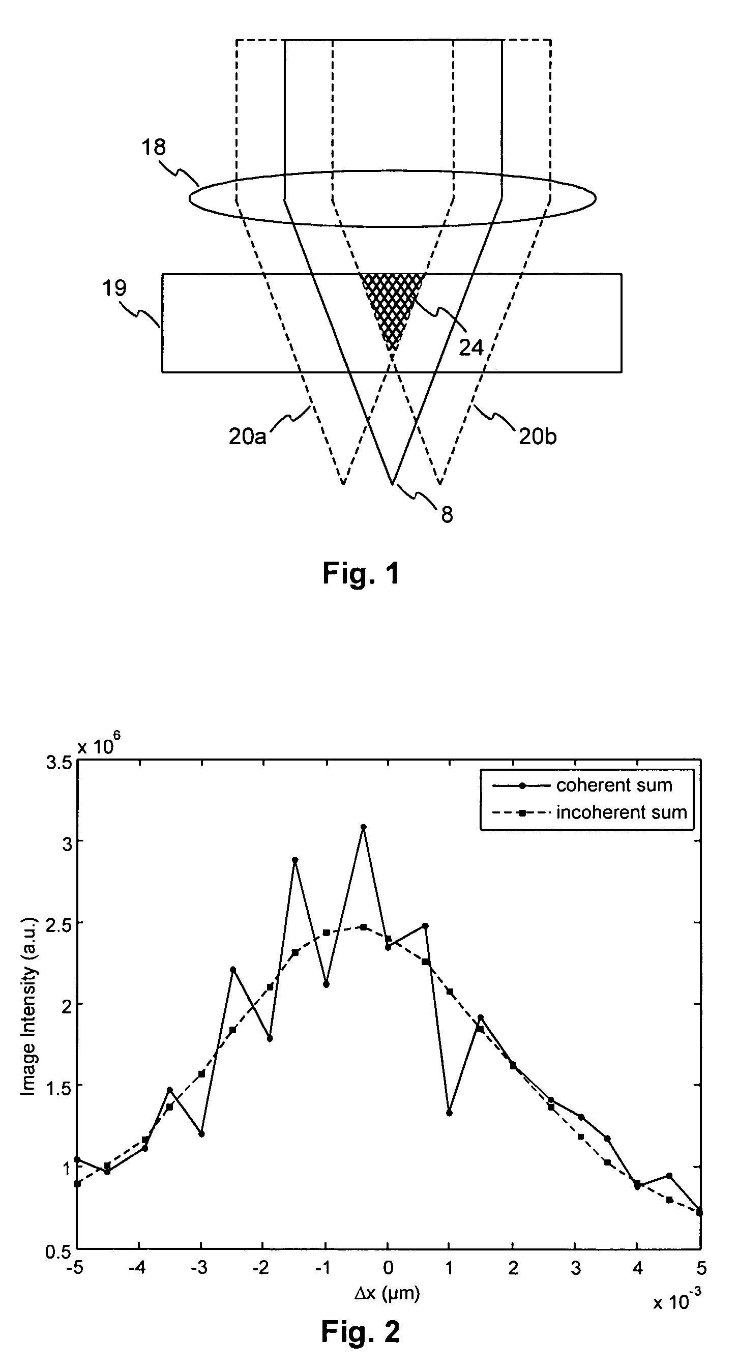
[0029]The overlap of multiple coherent reference beams 20a, 20b also causes disturbing effects during the reading operation. FIG. 2 shows measurements of the shift selectivity of a hologram written with the beam arrangement described above. The solid curve shows the intensity of a reconstructed data page in case of reading with two coherent reference beams 20a, 20b. The curve exhibits characteristic intensity fluctuations when shifting the material out of the nominal position, where the...


PUM


Abstract

An apparatus for reading from and / or writing to holographic storage media is described, and more specifically an apparatus for reading from and / or writing to holographic storage media with two or more reference beams that overlap inside the holographic storage medium for reading and / or writing a single hologram. The two or more reference beams are mutually incoherent during reading and / or writing.

Description

[0001]This application claims the benefit, under 35 U.S.C. §119 of EP Patent Application 08102721.1, filed 18 Mar. 2008.FIELD OF THE INVENTION[0002]The present invention relates to an apparatus for reading from and / or writing to holographic storage media, and more specifically to an apparatus for reading from and / or writing to holographic storage media with multiple reference beams.BACKGROUND OF THE INVENTION[0003]In holographic data storage digital data are stored by recording the interference pattern produced by the superposition of two coherent laser beams, where one beam, the so-called ‘object beam’, is modulated by a spatial light modulator and carries the information to be recorded. The second beam serves as a reference beam. The interference pattern leads to modifications of specific properties of the storage material, which depend on the local intensity of the interference pattern. Reading of a recorded hologram is performed by illuminating the hologram with the reference be...

Claims


Application Information

Patent Timeline
Patent Type & Authority Patents(United States)
IPC IPC(8): G03H1/10G03H1/12G03H1/28
CPCG11B7/0065G03H1/28G03H2222/20G11B7/1384
Inventor PRZYGODDA, FRANKKNITTEL, JOACHIM
Owner THOMSON LICENSING SA
Learn More