

A connecting apparatus for optical fibre
An optical fiber connection and connector technology, which is applied in the field of optical communication, can solve the problems of cumbersome, not small enough, and many production processes of parts, and achieves the effect of less parts, simple structure and production process, and saving of clamping parts.
- Summary
- Abstract
- Description
- Claims
- Application Information
AI Technical Summary
Problems solved by technology
Method used
Image

Examples
Embodiment Construction
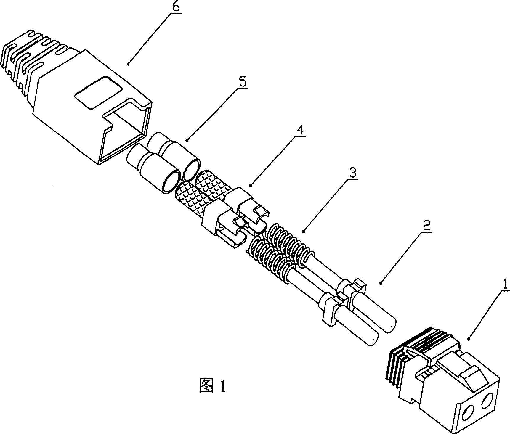
[0019] Referring to the accompanying drawings, its structure is that it includes two parts: a connector and an adapter device. There are two symmetrical openings on the adapter housing in the adapter device part, which are matched with the locking device on the connector housing 1 in the connector part; The connector housing 1 is equipped with two axial passage pins, the diameter of which is 2.5 mm or 1.25 mm, the length of the connector housing ≤ 45 mm, the width ≤ 12 mm, and the height ≤ 9 mm.
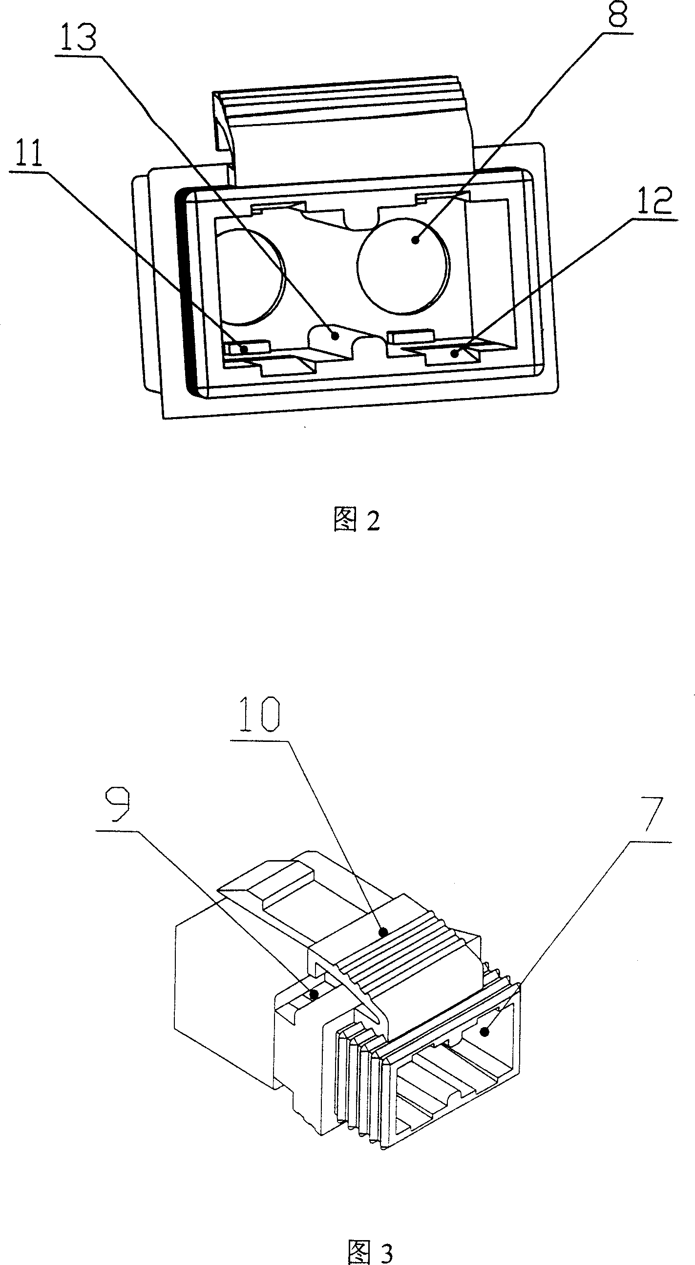
[0020] The connector part includes a connector housing 1, two cylindrical pins 2 with a diameter of 2.5 mm, a spring 3, a spring seat 4, a snap ring 5, a boot 6, a connector housing 1 with multiple inner surfaces, The housing 1 includes a first opening 7 for accommodating optical fibers and a second opening 8 for allowing the end face of the cylindrical ferrule to protrude through; four notches 9 for cooperating and fixing with the clamping device of the spring seat ; and a manually ...
PUM
| Property | Measurement | Unit |
|---|---|---|
| Diameter | aaaaa | aaaaa |
| Length | aaaaa | aaaaa |
| Width | aaaaa | aaaaa |
Abstract
Description
Claims
Application Information