A kind of controllable thread pulling nail with bushing

A technology of bushing and thread, which is applied in the design and manufacture of fasteners, can solve the problems of easy loosening and falling off, easy loosening, and difficult installation, so as to improve fatigue performance and anti-loosening performance, improve installation accuracy and integration degree high effect

Active Publication Date: 2018-02-06
AEROSPACE PRECISION PROD INC LTD
View PDF5 Cites 0 Cited by
  • Summary
  • Abstract
  • Description
  • Claims
  • Application Information

AI Technical Summary

Problems solved by technology

The existing blind rivets are only pressed on one side with the connected part, and are prone to loosening during frequent vibrations, and for the blind hole surface (after the traditional blind rivet is installed, the connected part and the blind rivet are deformed and formed The side of the bulge that is in contact with each other is opposite to the other side) The connected parts with a small inclination angle are often difficult to install, or they are easy to loosen and fall off after installation
[0004] In addition, the existing blind rivets are composed of three to five parts, and the structure is relatively complicated. Due to the large number of parts, it is easy to cause axial force deviation during the installation process of the blind rivet, resulting in the failure of the installation process. If the eccentric moment is too large, it will lead to unfavorable phenomena such as unstable installation, uneven twist-off groove port, and even damage to parts.
The general rotary blind rivet has a lock ring, which is used to fix the nail sleeve after the blind rivet is broken, so as to prevent the fixing part from falling off. Looseness occurs. In addition, in order to ensure the locking effect of the lock ring, it is necessary to precisely process the specifications of the lock ring, which increases the processing cost and assembly cost

Method used


Image

  • A kind of controllable thread pulling nail with bushing
  • A kind of controllable thread pulling nail with bushing
  • A kind of controllable thread pulling nail with bushing

Examples


Embodiment Construction

[0021] The invention will be further explained below in conjunction with the drawings.

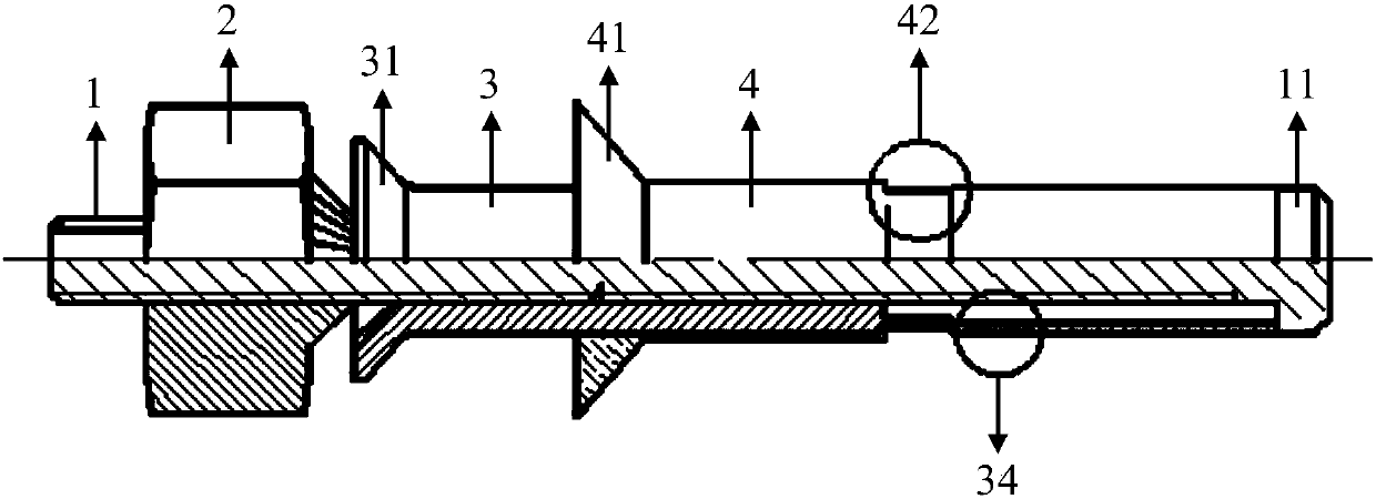
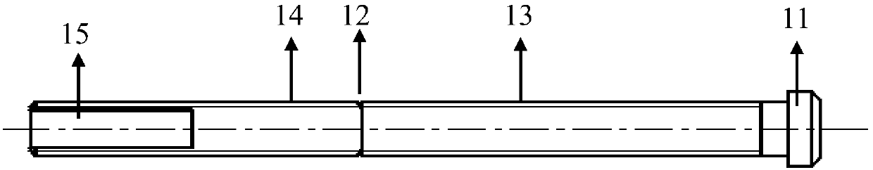
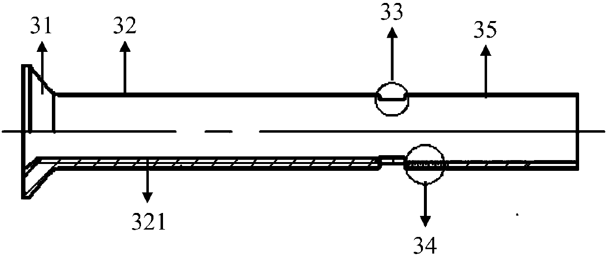
[0022] The invention creates a structure for an implementation such as Figure 1-5 As shown, it includes a core rod 1, a driving nut 2, a nail body 3, and a bushing 4. The core rod 1 is provided with a head protrusion 11 at one end and a neck-breaking groove 12 at the middle part; on the outer surface of the core rod 1 , From the side of the neck-breaking groove 12 facing the head protrusion 11, a first threaded section 13 is provided in the direction of the head protrusion 11; on the outer surface of the core rod 1, from the The neck-breaking groove 12 starts from one side toward the tail of the core rod 1 (that is, the other side opposite to the side facing the head protrusion 11), and is provided with a second side toward the tail of the core rod 1. Threaded section 14; the nail body 3 is sleeved on the core rod 1, and in turn has a nail body head 31, a nail body sleeve portion 32, an ann...


PUM


Abstract

The invention provides a controllable threaded fastener with a bush. The controllable threaded fastener comprises a core rod, a driving nut, a fastener body and the bush. The core rod is provided with a head convex body and a broken neck groove. A first threaded section and a second threaded section are arranged at the positions, at the two sides of the broken neck groove, of the outer surface of the core rod. The core rod is sleeved with the fastener body, and the fastener body is sequentially provided with a fastener body head portion, a fastener body sleeve portion, an annealing portion and a pipe portion. A sleeve thread engaged with the first threaded section is arranged in the fastener body sleeve portion, and the pipe portion is limited by the head convex body. The core rod is sleeved with the driving nut, a driving thread engaged with the second threaded section is arranged in the driving nut, and the driving nut can drive the fastener body to move towards the head convex body. The fastener body is fixedly sleeved with the bush, and the bush does not coincide with the annealing portion and the pipe portion of the fastener body. The controllable threaded fastener has good fatigue and loosening prevention performance, and is high in structure integration degree.

Description

Technical field [0001] The invention belongs to the technical field of fastener design and manufacturing, and particularly relates to a controllable threaded nail with a bushing. Background technique [0002] Nowadays, in aviation and aerospace vehicles, due to the strict control of their own weight, in order to reduce weight, many composite materials are used as the body material, and the installation space is often small and workers cannot successfully install it. In this case, blind rivets that can be used for single-sided riveting are usually used to realize the installation of composite materials and aluminum alloy structures. [0003] Spacecraft will inevitably receive shocks from the external environment such as airflow during installation, maintenance, flight, especially take-off and landing. In order to ensure the safety of the spacecraft, the fasteners are required to have good performance after installation. The fatigue and anti-loosing performance of the machine, and t...

Claims


Application Information

Patent Timeline
Patent Type & Authority Patents(China)
IPC IPC(8): F16B19/04
CPCF16B19/04
Inventor 刘智昂何文德王川唐伟桂林景郭双双郗建豪张晓玲
Owner AEROSPACE PRECISION PROD INC LTD
Why Eureka
Try Eureka