Intravascular stent of composite structure

A technology of composite structure and inner stent, applied in the field of intravascular stent with composite structure, can solve the problems of increasing the difficulty of operation, increasing the shortening rate of the stent, and difficult to maintain the designed shape of the stent, achieving superior bending resistance and fatigue performance and successful operation. The effect of improved efficiency and improved controllability

Inactive Publication Date: 2015-12-09
魏诗荣 +1
View PDF7 Cites 24 Cited by
  • Summary
  • Abstract
  • Description
  • Claims
  • Application Information

AI Technical Summary

Problems solved by technology

[0003] The Solitaire FRDevice of the American ev3 company and the TrevoRetriever of the American Stryker company have two common shortcomings in actual clinical use: 1) Both of them have no distal vascular protection design, and small thrombus will peel off from the main body and flow to the more distal end during use. blood vessels, thereby blocking smaller blood vessels, causing secondary strokes, and even endangering the patient's life
Larger braiding density will bring higher radial force, but the braiding density increases, the fore-shortening rate of the stent increases, and the release of the stent is difficult; on the other hand, if the braiding density is too small, it is difficult for the stent to maintain the design shape
A larger number of braided filaments will increase the radial force, but an increase in the number of braided filaments will require the use of a larger delivery catheter and increase the difficulty of the operation
Increasing the diameter of the braided wire will also increase the radial force, but the increase in the diameter of the braided wire will also require the use of a larger delivery catheter and increase the difficulty of the operation; on the other hand, the braided wire with a smaller diameter is more likely to break after long-term use
Braided wire with higher stiffness and elastic modulus will bring higher radial force; on the other hand, too high radial force of the stent will cause damage to the soft cerebral blood vessels

Method used


Image

  • Intravascular stent of composite structure
  • Intravascular stent of composite structure
  • Intravascular stent of composite structure

Examples


Embodiment 1

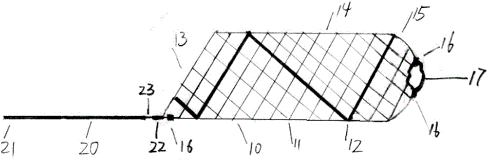
[0051] Such as figure 1 The stent of the present invention is shown as a thrombus removal device for treating acute cerebral apoplexy. The doctor slowly pushes the catheter with the stent 10 inside to pass through the thrombus, and then presses the proximal end 21 of the delivery guide wire 20 fixed together with the stent, and slowly The catheter is withdrawn slowly so that the stent is released and the thrombus is contained. At this time, the delivery guide wire 20 is slowly withdrawn, and finally the thrombus is sent to a guide catheter with a larger inner diameter, and the guide catheter with thrombus is withdrawn from the patient's body. Because the distal end 15 of the stent is retracted, even when the guide wire 20 is retracted, a small thrombus may break away from the main thrombus. Flow to small distal vessels, causing more vessel blockages. After the thrombus was taken out, the patient's blood flow was unblocked immediately, and the symptoms were relieved. When us...

Embodiment 2

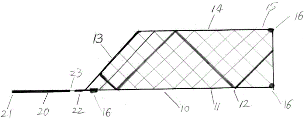
[0053] The stent of the present invention is used as a stent to expand narrow or blocked blood vessels, such as figure 2 As shown, the doctor infuses the catheter with the stent 10 pressed inside through the narrow blood vessel, then presses the proximal end 21 of the delivery guide wire 20 fixed with the stent, and slowly withdraws the catheter. At this time, the stent starts from the distal end. It is gradually released to dilate the narrowed blood vessels, and the patient's blood flow is immediately dredged, and the symptoms are relieved. If the doctor is not satisfied with the position of the stent, he can withdraw the stent to the catheter, readjust the position of the catheter, and then release the stent again. Finally, the middle part of the stent is placed on the narrowed blood vessel. Due to the expansion and support of the stent, the actual inner diameter of the narrowed blood vessel increases and the blood flow increases. Gradually increased, the patient's symptoms...

Embodiment 3

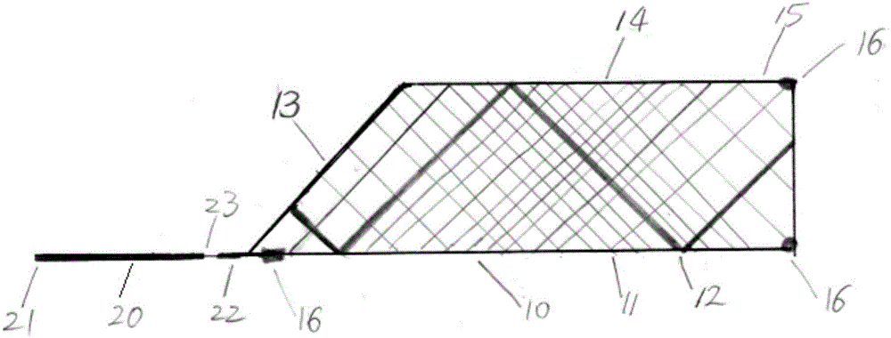
[0055] When the stent is placed in the blood vessels of the lower extremities (such as the femoral artery, hip artery, popliteal artery, etc.), it is very challenging. When people walk or squat, the stent will be greatly compressed and bent. Once the stiffness and bending resistance of the stent are poor , the probability of stent fracture is high. A specially designed stent of the present invention is very suitable for dilating narrowed lower extremity blood vessels. Such as image 3 As shown, it is characterized in that the weaving density of the main body of the stent is greater than that of the two ends. The characteristics of braided stents are that the higher the braiding density, the stronger the stiffness of the stent, the higher the radial force of the stent, and the better the bending resistance of the stent.


PUM

PropertyMeasurementUnit
diameteraaaaaaaaaa
diameteraaaaaaaaaa
thicknessaaaaaaaaaa

Abstract

The invention discloses an intravascular stent of a composite structure; the intravascular stent comprises a stent main body, wherein the distal end of the stent is restrained as an adducted form by virtue of a tightening wire, and the tightening wire is degradable magnesium alloy or degradable iron alloy; one or more auxiliary wires are woven on the stent main body; when the stent is applied to blood vessel of brain, the auxiliary wire is pure platinum or alloy thereof, pure gold or alloy thereof, pure tungsten or alloy thereof, or pure tantalum or alloy thereof; and when the stent is applied to peripheral blood vessel, the auxiliary wire is cobalt-chromium alloy or stainless steel or tungsten or tantalum. The stent, when serving as a thrombus removal system for treating cerebral apoplexy, not only can be used for removing thrombus effectively for several times but also can be used for catching small thrombus flowing to distal end so as to prevent distal blood vessels from getting blocked; and the stent can be used for dilating stenosis or blocked brain blood vessel or peripheral blood vessel, so as to take an effect of dredging and reconstructing a blood flow. The stent can be repositioned and released, with high controllability; and the stent can be used for reducing operation difficulty and greatly improving an operation success rate.

Description

technical field [0001] The invention relates to a composite structure intravascular stent, which belongs to the technical field of medical devices. Background technique [0002] Cerebral stroke is the most serious refractory disease that endangers human health and life safety. According to statistics, there are 3 million stroke patients in China every year, and 1.2 million stroke patients die every year. There are 8 million survivors of stroke, 6 million of whom have lost their labor force and are unable to take care of themselves to varying degrees. For patients with cerebral apoplexy who are sent to the hospital in time, the conventional treatment plan is drug thrombolysis, but the active ingredients of many drugs are difficult to reach the lesion, and it is difficult to ablate large thrombus, so that the intended treatment purpose cannot be achieved. Secondly, the best window time for drug thrombolysis (the time from the onset of the disease to the time of treatment) is ...

Claims


Application Information

Patent Timeline
Patent Type & Authority Applications(China)
IPC IPC(8): A61F2/90A61F2/966A61L31/02
Inventor 魏诗荣吕文峰
Owner 魏诗荣
Why Eureka
Try Eureka