A composite function intravascular stent

A composite function and internal stent technology, applied in the field of composite functional endovascular stents, can solve the problems of difficult interventional operations, endangering the lives of patients, and patients' dangers, and achieve the goal of improving the success rate of operations, fast and efficient removal, and filling the gap in the market Effect

Inactive Publication Date: 2015-09-16
吕文峰 +2
View PDF11 Cites 0 Cited by
  • Summary
  • Abstract
  • Description
  • Claims
  • Application Information

AI Technical Summary

Problems solved by technology

However, such an interventional operation is very difficult, the success rate is not high, and the long-term effect is not good, because two round tube-shaped stents placed side by side occupy most of the vascular space. Stenosis or even blockage of the blood vessel will occur in most of the stents, which will bring fatal danger to the patient
[0006] The Solitaire FR Device of the American ev3 company and the Merci Retrieval Device of the American Concentric Medical Company have several major shortcomings in common in actual clinical use: 1) Both of them have no distal vascular protection design, and small thrombus will peel off from the main body during use. Flow to more distal blood vessels, thereby blocking smaller blood vessels, causing secondary strokes, and even endangering the patient's life
However, the fatal disadvantage of this stent is that the wires at both ends are all tied tightly in the developing ring, forming a densely woven structure at both ends of the stent, so that after the blood flow enters the proximal end of the stent, the flow rate is greatly reduced, thereby promoting the formation of thrombus in the stent, resulting in In-stent occlusion, which also gradually occludes the vessel, poses a significant risk to the patient

Method used


Image

  • A composite function intravascular stent
  • A composite function intravascular stent
  • A composite function intravascular stent

Examples


Embodiment 1

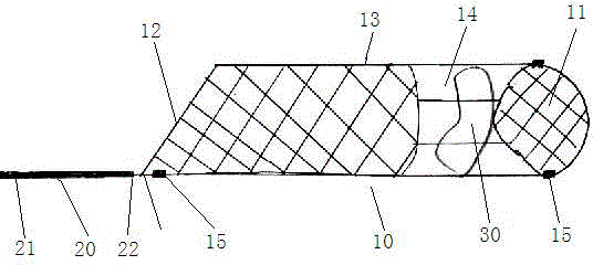
[0047] If the stent of the present invention is used as an acute thrombus removal device, the doctor slowly pushes the catheter (or microcatheter) with the stent 10 inside to pass through the thrombus 30, and then presses the proximal end 21 of the delivery guide wire 20 fixed together with the stent, Withdraw the microcatheter slowly, as image 3 As shown, the stent is released and contains the thrombus 30 like this. At this time, the delivery guide wire 20 is slowly withdrawn, and finally the thrombus is sent to a guide catheter with a larger inner diameter, and the guide catheter with thrombus is withdrawn from the patient's body. The patient's blood flow was unblocked and the symptoms were relieved.

Embodiment 2

[0049] If the stent of the present invention is used as a temporary stent to quickly dredge narrow or blocked blood vessels, such as Figure 4 As shown, the doctor can send the microcatheter equipped with the stent 10 of the present invention to the more distal position of the narrowed or blocked blood vessel 40, then press the delivery guide wire 20 fixed with the stent, and slowly withdraw the microcatheter , so that the bracket is released. If the doctor is not satisfied with the position of the stent, he can withdraw the stent to the microcatheter, readjust the position of the microcatheter, and then release the stent again, and finally place the middle part of the stent on the narrowed blood vessel. Due to the expansion and support of the stent, the actual inner diameter of the narrowed blood vessel increases. Blood flow gradually increased, and the patient's symptoms eased. Generally, blood flow can be fully restored after about 30 minutes to 120 minutes. After achievi...

Embodiment 3

[0053] If the stent of the present invention is used as a permanent implant stent 10 to assist in releasing the microcoil, the doctor can send the microcatheter with the stent of the present invention inside the bifurcation aneurysm 50 of the main blood vessel 70 and branch blood vessels 71, and then Press and hold the delivery guide wire 20 that is fixed together with the stent, and slowly retract the microcatheter, so that the stent is released, such as Figure 5 , by observing the position of the development ring (or development coil) 15 at the distal end of the stent 11, it is ensured that the umbrella-shaped (or barrel-shaped) structure at the distal end of the stent is just positioned at the neck of the aneurysm 50. If the doctor is dissatisfied with the position of the stent, the stent can be withdrawn into the microcatheter, the position of the microcatheter is readjusted, and then the stent is released again. Finally, the umbrella (or barrel) structure at the distal en...


PUM

PropertyMeasurementUnit
diameteraaaaaaaaaa
diameteraaaaaaaaaa
thicknessaaaaaaaaaa

Abstract

The invention discloses an intravascular stent with complex functions. The intravascular stent comprises a stent main body which is mesh-shaped and can be released from and retracted to a feeding catheter, wherein a near end of the stent main body is openly conical, the middle part of the stent main body is circular tube-shaped, and a far end of the stent main body has a closed structure; and the stent main body has a mesh shape which is woven by single wires or a plurality of wires or is engraved by a laser engraving machine. The stent which is taken as an acute thrombus removal system can quickly and efficiently take out thrombi, and can also capture small thrombi which flow toward the far end so as to avoid secondary stroke caused by the thrombus blockage of the far end; the stent which is taken as a temporary stent expands intracranial blood vessels or narrow and blocked blood vessels on other parts of human bodies, plays the effects of dredging and reconstructing blood flow, and can capture small thrombi or emboli; and the stent which is taken as a long-term implanted stent performs adjuvant therapy on arterial aneurysms of furcations, and fills in a market gap. If the position of the stent is not satisfactory, the entire stent can be retracted to the feeding catheter, and is released again. The maneuverability of the stent is high, so the operation difficulty is reduced, and the surgical success rate is greatly improved.

Description

technical field [0001] The invention relates to a composite function intravascular stent, which belongs to the technical field of medical devices. Background technique [0002] Stroke is a refractory disease that seriously endangers human health and life safety. According to statistics, there are 2.8 million stroke patients in China every year, and 1.5 million stroke patients die every year. There are 8 million survivors of stroke, 6 million of whom have lost their labor force and are unable to take care of themselves to varying degrees. For patients with cerebral apoplexy who are sent to the hospital in time, the conventional treatment plan is drug thrombolysis, but the active ingredients of many drugs are difficult to reach the lesion, so that the intended treatment purpose cannot be achieved. Secondly, the best window time for drug thrombolysis (the time from the onset of the disease to the time of treatment) is within 4 hours. Since most of the patients in our country l...

Claims


Application Information

Patent Timeline
Patent Type & Authority Patents(China)
IPC IPC(8): A61F2/90A61B17/12A61L31/18A61L31/02
Inventor 吕文峰张翠欣魏诗荣
Owner 吕文峰
Why Eureka
Try Eureka