Organic electroluminescent element and lighting device

an electroluminescent element and lighting device technology, applied in the direction of triarylamine dyes, perylene derivatives, anthracene dyes, etc., can solve the problems of poor flatness of the interface between the light-extraction layer and the transparent electrode, and the light trapped in the device cannot be extracted, so as to achieve high light-extraction efficiency and high luminance

Active Publication Date: 2012-11-15
IDEMITSU KOSAN CO LTD
View PDF2 Cites 94 Cited by
  • Summary
  • Abstract
  • Description
  • Claims
  • Application Information

AI Technical Summary

Benefits of technology

[0067]Since the organic electroluminescence device according to the above aspect of the invention exhibits a high light-extraction efficiency, an illumination unit with a high luminance can be provided.

Problems solved by technology

However, the light trapped within the device cannot be extracted only by adjusting the optical coherence length.
Incidentally, the method used in Patent Literature 2 provides poor flatness of the interface between the light-extraction layer and the transparent electrode.

Method used


Image

  • Organic electroluminescent element and lighting device
  • Organic electroluminescent element and lighting device
  • Organic electroluminescent element and lighting device

Examples


first exemplary embodiment

[0091]A first exemplary embodiment of the invention will be described below with reference to the attached drawings.

Organic Electroluminescence Device

[0092]FIG. 4 is a cross section in a thickness direction of an organic electroluminescence device (referred to as organic EL device hereinafter) according to a first exemplary embodiment of the invention, where a part of the cross section is enlarged.

[0093]The organic EL device 1 is provided by laminating a light-transmissive substrate 2, a light-extraction layer 3, a transparent electrode 4, an organic emitting layer 5 and an opposing electrode 6 in this sequence.

Light-Transmissive Substrate

[0094]The light-transmissive substrate 2 is a flat smooth plate member for supporting the light-extraction layer 3, the transparent electrode 4, the organic emitting layer 5 and the opposing electrode 6. The organic EL device 1 is a so-called bottom-emission device in which the radiation light generated in the organic emitting layer 5 is extracted ...

second exemplary embodiment

[0137]Next, a second exemplary embodiment of the invention will be described below with reference to the attached drawings.

Organic Electroluminescence Device

[0138]FIG. 7 is a cross section in a thickness direction of an organic EL device 40 according to the second exemplary embodiment of the invention, where a part of the cross section is enlarged.

[0139]The organic EL device 40 according to the second exemplary embodiment has a structure similar to that of the organic EL device 1 according to the first exemplary embodiment except for an electron transporting zone 41 provided between the organic emitting layer 5 and the opposing electrode 6 of the organic EL device 1 and a hole transporting zone 42 provided between the organic emitting layer 5 and the transparent electrode 4. Specifically, the organic EL device 40 is provided by laminating the light-transmissive substrate 2, the light-extraction layer 3, the transparent electrode 4, the hole transporting zone 42, the organic emitting...

third exemplary embodiment

[0163]Next, a third exemplary embodiment of the invention will be described below with reference to the attached drawings.

Organic EL Device

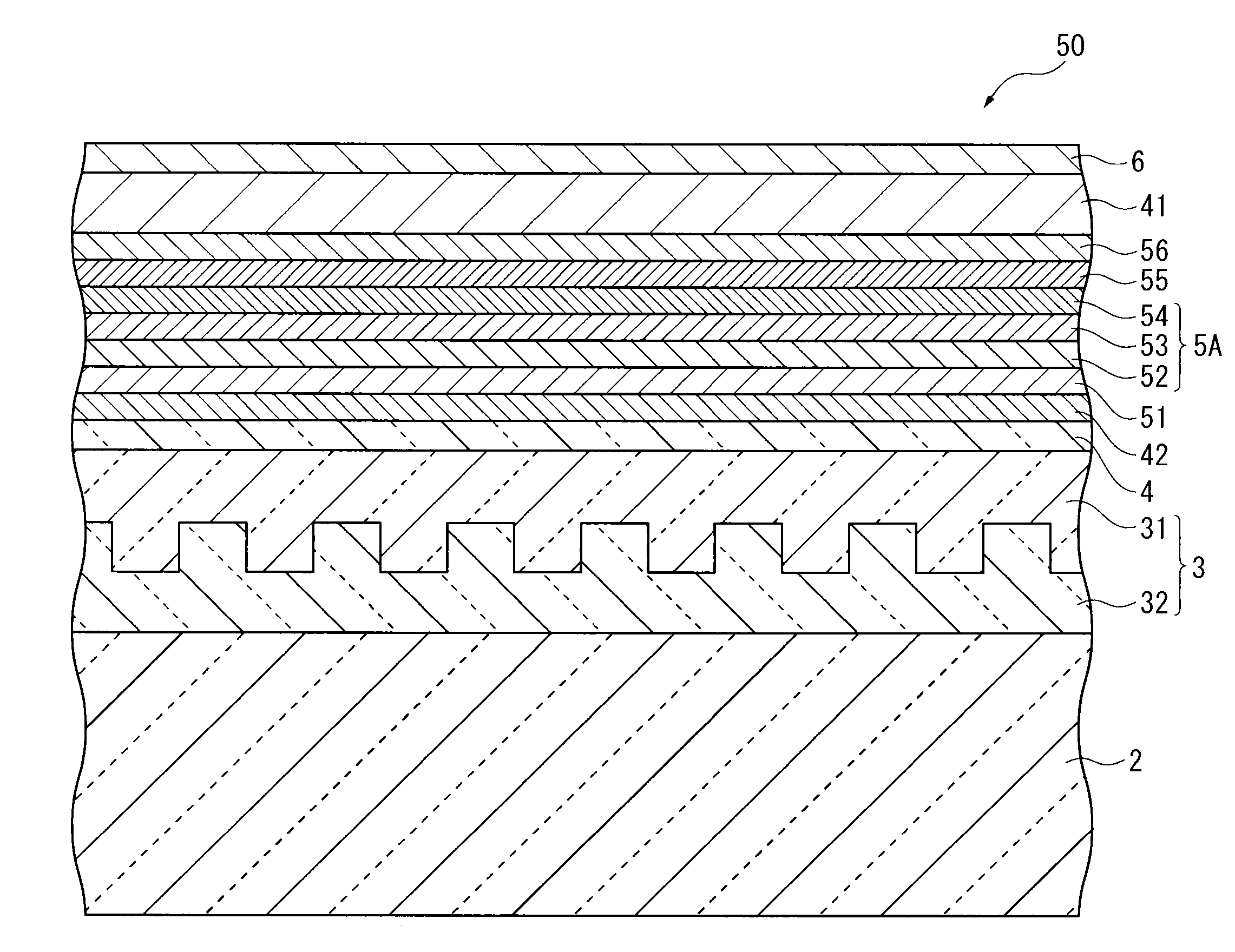
[0164]FIG. 10 is a cross section in a thickness direction of an organic EL device 50 according to the third exemplary embodiment of the invention, where a part of the cross section is enlarged.

[0165]The organic EL device 50 according to the third exemplary embodiment has a structure similar to that of the organic EL device 40 according to the second exemplary embodiment except for an intermediate unit 5A provided between the electron transporting zone 41 and the transparent electrode 4 of the organic EL device 40 and a plurality of organic emitting layers 51, 55 and 56 sandwiching the intermediate unit 5A. Specifically, the organic EL device 50 is provided by laminating the light-transmissive substrate 2, the light-extraction layer 3, the transparent electrode 4, the hole transporting zone 42, the first organic emitting layer 51, the intermediate...


PUM

PropertyMeasurementUnit
width d3aaaaaaaaaa
width d3aaaaaaaaaa
thicknessaaaaaaaaaa

Abstract

An organic EL device (1) comprises: a light-transmissive substrate (2); a transparent electrode (4); an organic emitting layer (5); and an opposing electrode (6). A light-extraction layer (3) provided by layering a high refractive index layer (31) adjoining the transparent electrode (4) and a low refractive index layer (32) adjoining the light-transmissive substrate (2) includes recess-protrusion units (31A) each provided by a protrusion (311) and a recess (312) at an interface between the high refractive index layer (31) and the low refractive index layer (32). In at least one of the recess-protrusion units (31A), a distance d1 from the interface between the high refractive index layer (31) and the low refractive index layer (32) to an interface between the transparent electrode (4) and the high refractive index layer (31) is equal to or more than an optical coherence length and a height d2 of the protrusion (311), a width d3 of the protrusion (311) and a gap d4 between the protrusion (311) and another protrusion (311) adjoining the protrusion across the recess (312) is 1 μm or more.

Description

TECHNICAL FIELD[0001]The present invention relates to an organic electroluminescence device and an illumination unit.BACKGROUND ART[0002]An organic electroluminescence device including an organic thin-film layer (in which an emitting layer is included) between an anode and a cathode, has been known to emit light using exciton energy generated by a recombination at the organic thin-film layer of holes injected from the anode into the emitting layer and electrons injected from the cathode into the emitting layer.[0003]Such an organic electroluminescence device, which has the advantages as a self-emitting device, is expected to serve as an emitting device excellent in luminous efficiency, image quality, power consumption and thin design.[0004]In an optical design of such an organic electroluminescence device, an optical coherence length is adjusted in order to enhance luminous efficiency. By adjusting a thickness of organic layers such as a hole transporting layer, the luminous efficie...

Claims


Application Information

Patent Timeline
Patent Type & Authority Applications(United States)
IPC IPC(8): H01L51/52
CPCC09K11/06H01L51/5268H01L51/5275H01L2251/5369H01L2251/558C09B3/14C09B57/00C09B57/008C09B1/00C09B3/02H05B33/12H10K50/854H10K50/858H10K2102/331H10K2102/351H10K50/11
Inventor NARAOKA, RYOFUKUDA, MASAHIKOKUMA, HITOSHI
Owner IDEMITSU KOSAN CO LTD
Why Eureka
Try Eureka