High-performance pressure vessel and carbon fiber for pressure vessel

Active Publication Date: 2006-07-27
MITSUBISHI CHEM CORP
View PDF2 Cites 25 Cited by
  • Summary
  • Abstract
  • Description
  • Claims
  • Application Information

AI Technical Summary

Benefits of technology

[0014] The present invention aims to provide a pressure vessel which is superior in both of fatigue properties a

Problems solved by technology

However, steel storage vessels are heavy in weight, and much labor for movement, transport and the like is required.
However, in the case in which pressure vessels having, for example, a burst pressure (breakage pressure) of more than 65 MPa are manufactured, the rate of occurrence of the strength of the reinforcing fibers tends to decline.
Consequently, it is necessary to thickly wind the reinforcing fibers as a counte

Method used


Image

  • High-performance pressure vessel and carbon fiber for pressure vessel
  • High-performance pressure vessel and carbon fiber for pressure vessel
  • High-performance pressure vessel and carbon fiber for pressure vessel

Examples


embodiments

[0063] The pressure vessel of the present invention is described below by means of specific embodiments.

[0064] The evaluation techniques for the reinforcing fibers are as follows.

(Strand Strength, Elastic Modulus, Tensile Elongation)

[0065] These were evaluated in conformity with JIS R7601.

[0066] Strand strength was divided by strand elastic modulus so as to calculate tensile elongation.

(Average Diameter of Filament Cross-Section of Carbon Fiber Tow)

[0067] First, using the yield, density and number of filaments (filament quantity) of the fiber tow, the average cross-sectional area of a filament cross-section of a carbon fiber tow was calculated from the following Formula (1).

[0068] The yield of the fiber tow is the mass per unit length of the carbon fiber tow (fineness), and was measured in conformity with JIS R7601.

[0069] The density of the fiber tow was measured by the density gradient tube method in conformity with JIS R7601. Aav=1n⨯tp⨯10-3Formula⁢ ⁢(1)

[0070] Aav: avera...

first embodiment

[0095] A pressure vessel having a normal filling pressure of 70 MPa was prepared by the following procedure.

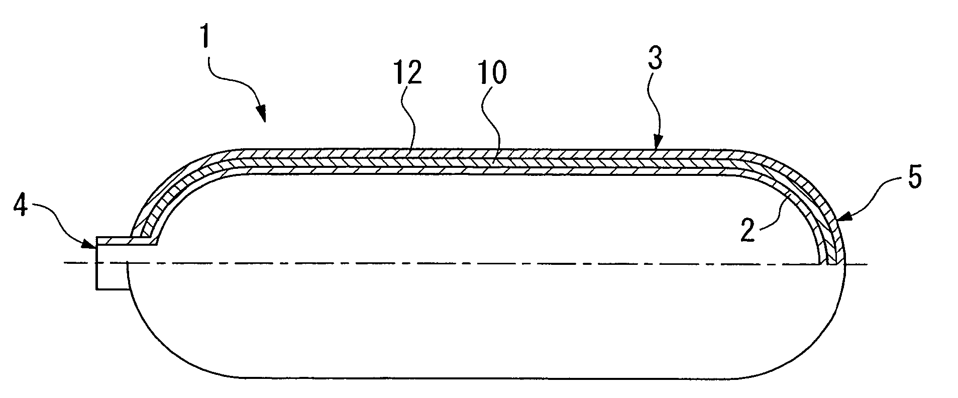
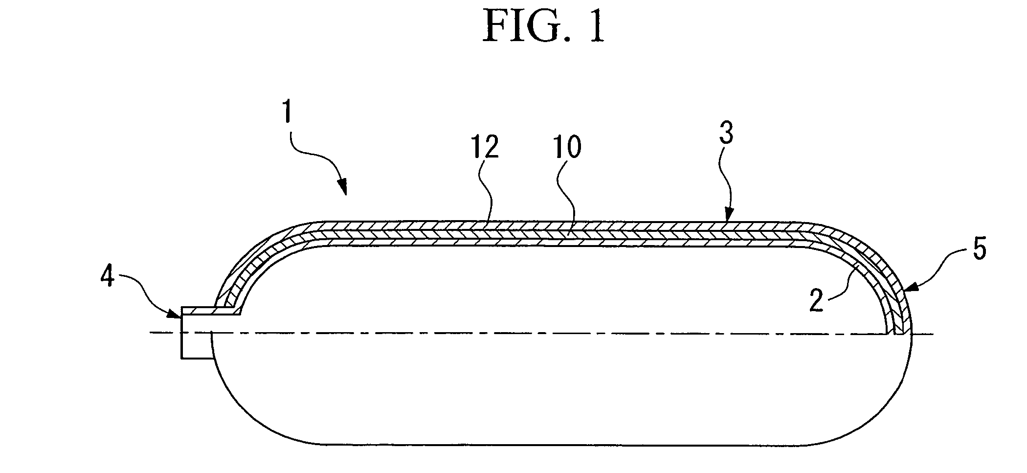
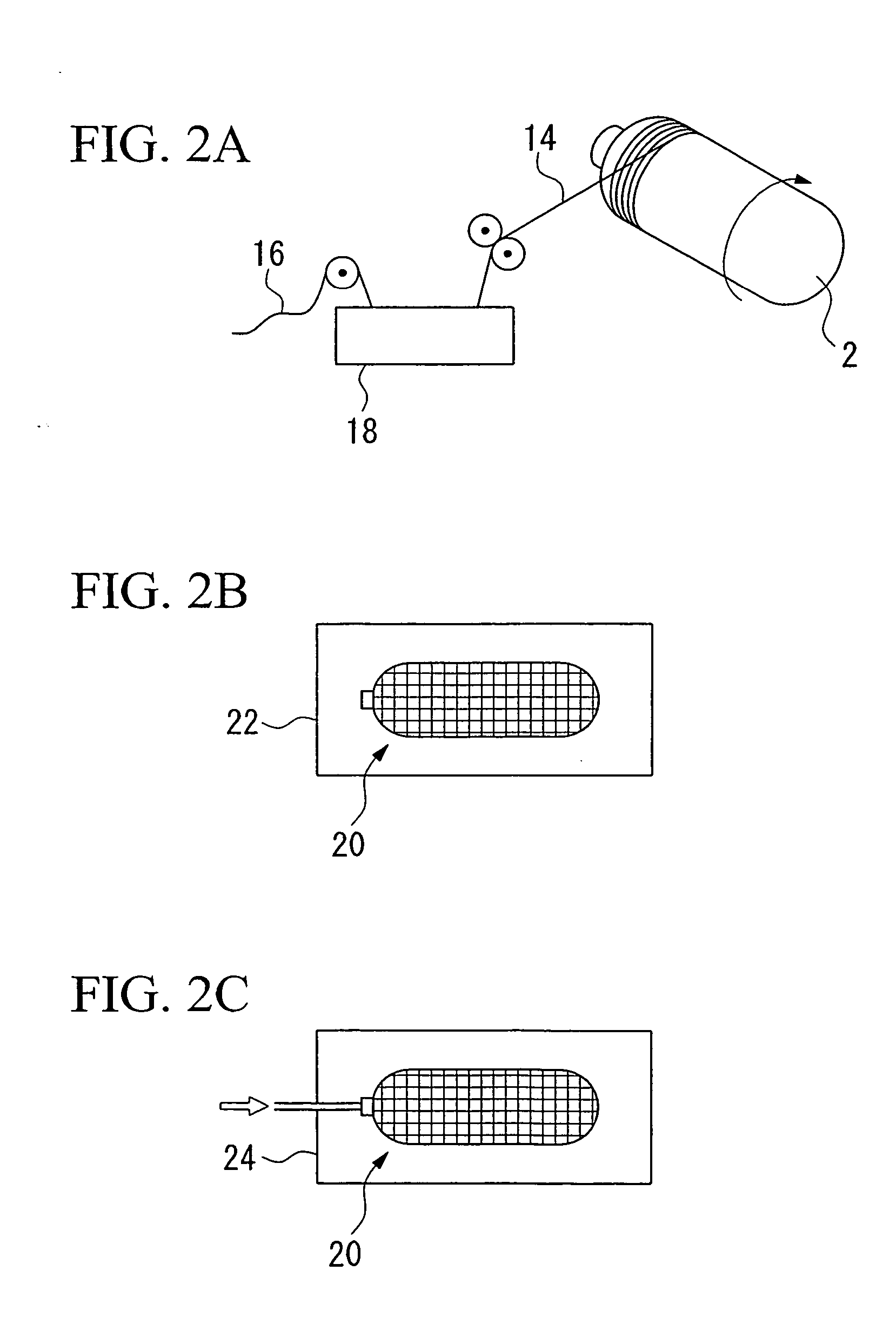
[0096] As shown in FIG. 2A, the reinforcing fibers (i) (elongation: 1.50%, elastic modulus: 350 GPa) were impregnated with matrix plastic so as to obtain the fiber reinforced plastic 14. Using a filament winding machine manufactured by Entec Composite Machines, Inc., the fiber reinforced plastic 14 was wound onto the vessel body 2, and fiber reinforced plastic layers of 5-layer structure were formed.

[0097] The fiber reinforced plastic layers had a five-layer structure of circumferentially oriented layer (C) / axially oriented layer (H) / circumferentially oriented layer (C) / axially oriented layer (H) / circumferentially oriented layer (C) in the order in which they were arranged from the inside (vessel body side) toward the outside (outer side).

[0098] In the obtained intermediate vessel 20, measurement result of the thickness of the fiber reinforced plastic layers at the center o...

second embodiment

[0112] A pressure vessel having a normal filling pressure (FP) of 70 MPa was prepared by the following procedure.

[0113] In the similar way as that in the first embodiment, fiber reinforced plastic layers having the fiber reinforced plastic 14 in which the reinforcing fibers (ii) (elongation: 1.64%, elastic modulus: 320 GPa) were impregnated with matrix plastic, were formed on the vessel body 2 so as to obtain the intermediate vessel 20.

[0114] The fiber reinforced plastic layers had the same 5-layer structure as that of the first embodiment. In the intermediate vessel 20, measurement result of the thickness of the fiber reinforced plastic layers at the center of the cylindrical section was approximately 13 mm.

[0115] The intermediate vessel 20 was subjected to heat treatment in the same way as that in the first embodiment. The mass of the fiber reinforced plastic layers was 5,633 g.

[0116] Next, the intermediate vessel 20 was subjected to autofrettage treatment in the same way as t...


PUM

PropertyMeasurementUnit
Pressureaaaaaaaaaa
Diameteraaaaaaaaaa
Heightaaaaaaaaaa

Abstract

A pressure vessel includes a vessel body and a fiber reinforced plastic layer formed on the surface of the vessel body, wherein the fiber reinforced plastic layer include fiber reinforced plastic in which reinforcing fibers are impregnated with plastic, a strand elastic modulus of the reinforcing fiber is 305 GPa or higher, and a tensile elongation of the reinforcing fiber is 1.45 to 1.70%. A carbon fiber for a pressure vessel has a strand elastic modulus of 305 GPa or higher and a tensile elongation of 1.45 to 1.70%.

Description

TECHNICAL FIELD [0001] The present invention relates to a pressure vessel used as a storage vessel for high-pressure gas and the like, and to carbon fibers used therein. [0002] This application claims priority from Japanese Patent Application No. 2003-305228 filed Aug. 28, 2003, the content of which is incorporated herein by reference. BACKGROUND ART [0003] Conventionally, containers made of steel are generally used as storage vessels for high-pressure gas. [0004] However, steel storage vessels are heavy in weight, and much labor for movement, transport and the like is required. [0005] For example, for automobiles using gaseous fuel, lighter-weight fuel storage vessels are required for the purpose of reducing vehicle weight in order to keep the fuel consumption amount low. [0006] As storage vessels for high-pressure gas, instead of the conventional steel storage vessels, pressure vessels made of composite material in which liner material (vessel body) of plastic or metal is strength...

Claims


Application Information

Patent Timeline
IPC IPC(8): F17C1/00F17C1/06F17C1/16
CPCF17C1/06Y10T428/30F17C2201/0109F17C2201/056F17C2203/0604F17C2203/0619F17C2203/0621F17C2203/0624F17C2203/0636F17C2203/0646F17C2203/0648F17C2203/066F17C2203/0665F17C2203/0668F17C2203/0673F17C2209/2154F17C2209/232F17C2223/0123F17C2223/036F17C2260/011F17C2260/012F17C2260/017F17C2270/0178Y10T428/1362F17C1/16
Inventor SUGIURA, NAOKINAGATSUKA, SATOSHITAKEMOTO, HIDEHIROMATSUMOTO, MAKOTOSUGIURA, MASAYUKI
Owner MITSUBISHI CHEM CORP
Why Eureka
Try Eureka