

Hot Forging Facility
- Summary
- Abstract
- Description
- Claims
- Application Information
AI Technical Summary
Benefits of technology
Problems solved by technology
Method used
Image

Examples
examples
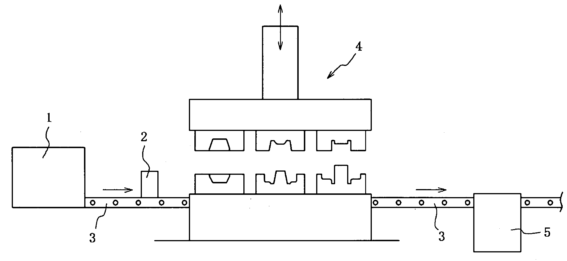
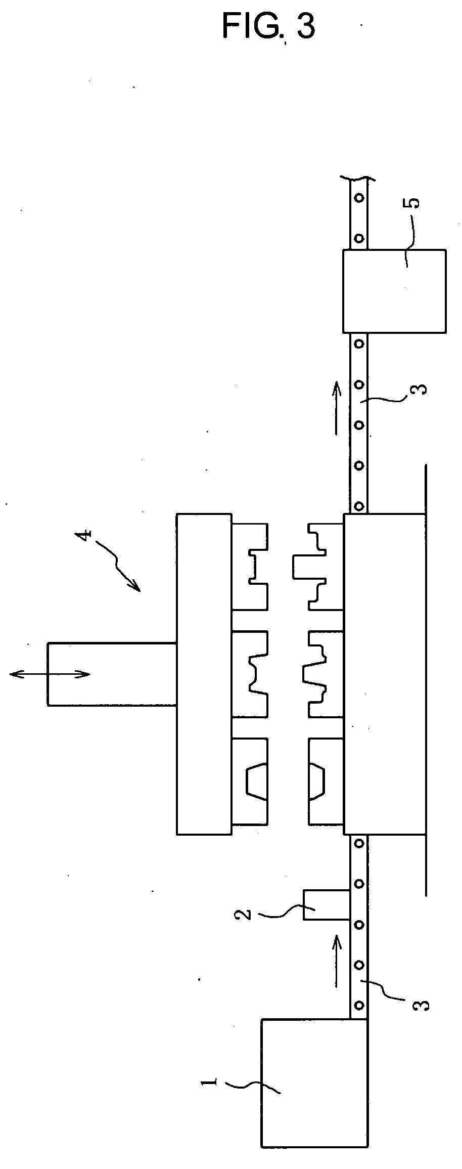
[0065]Steels of chemical compositions shown in Table 1 are refined in a vacuum melting furnace, and are molded into 100 kg ingots. Subsequently, the respective ingot is formed into a 65 mm diameter steel bar by hot forging, and then the steel bar is led into the hot forging facility. First, the steel bar was heated up to 1200° C. in the heating furnace 1, and then was subjected to three hot forging steps as shown in FIGS. 4(b) to 4(d) in the hot forging apparatus 4. Thereby, a forged product 20 having a flange, as shown in FIG. 4(d), were formed. The forged product 20 was immediately transported into the partially cooling apparatus 5 shown in FIG. 5. Then, partial cooling localized to flange base portions 20a was effected by injecting the cooling water at a flow range of 10˜201 / min, and then was subjected to radiational cooling. The start temperature of the partially cooled area was set to 780˜1150° C.
[0066]The respective hot forged product thus obtained was subjected structure obse...
PUM
| Property | Measurement | Unit |
|---|---|---|
| Temperature | aaaaa | aaaaa |
| Temperature | aaaaa | aaaaa |
| Temperature | aaaaa | aaaaa |
Abstract
Description
Claims
Application Information