High-strength free-cutting copper alloy and method for producing high-strength free-cutting copper alloy

a high-strength, free-cutting technology, applied in the field of high-strength free-cutting copper alloys, can solve the problems of bi being harmful to the human body, 1 has a problem in corrosion resistance, and pb is replaced by pb, so as to improve machinability and improve function, the effect of poor corrosion resistance, and poor impact resistan

Active Publication Date: 2021-10-26
MITSUBISHI MATERIALS CORP
View PDF43 Cites 0 Cited by
  • Summary
  • Abstract
  • Description
  • Claims
  • Application Information

AI Technical Summary

Benefits of technology

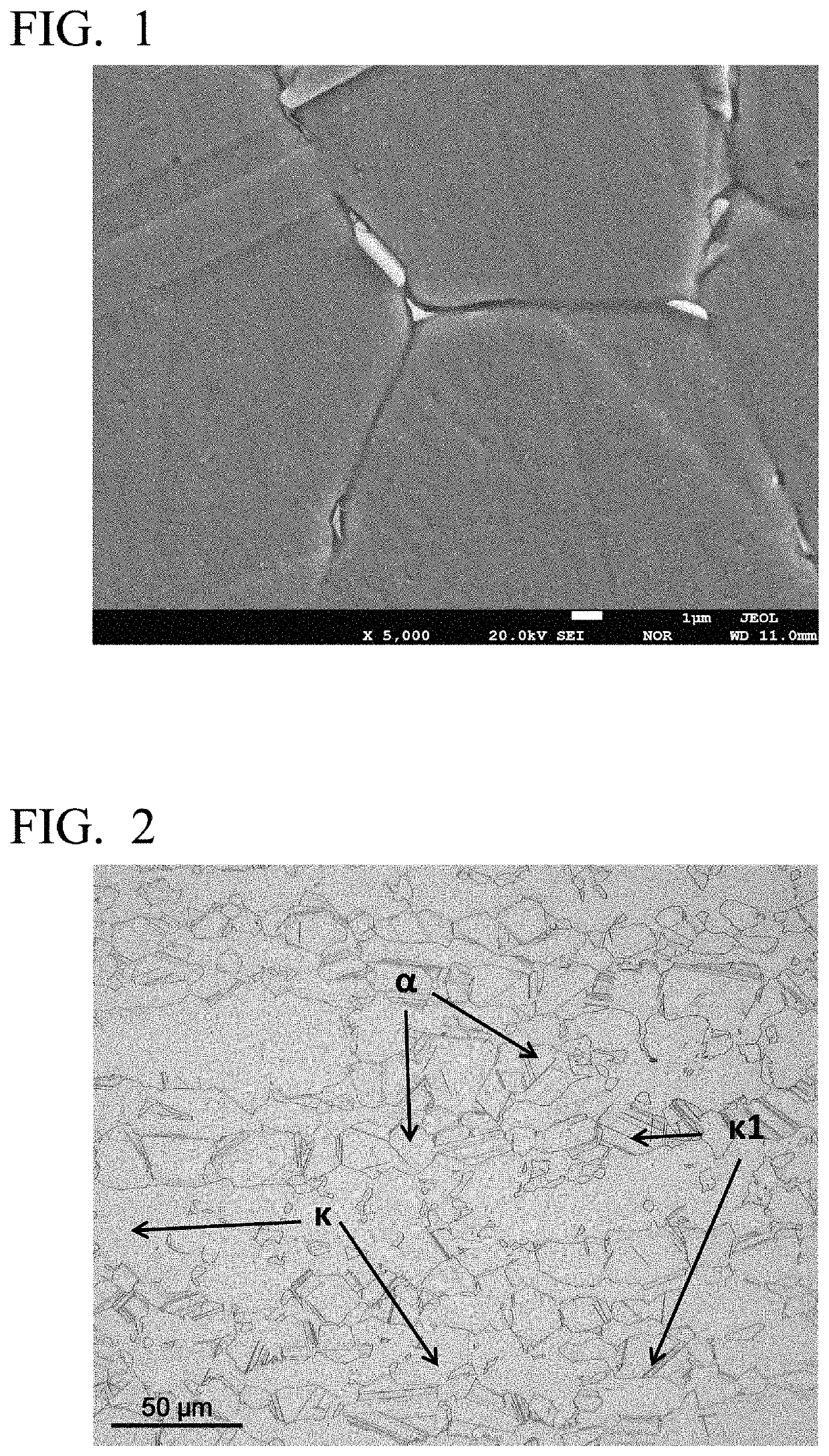
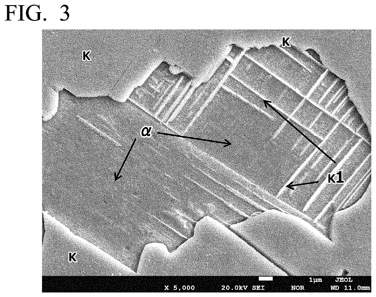
[0107]According to the aspects of the present invention, a metallographic structure in which γ phase that has an excellent machinability-improving function but has poor corrosion resistance, ductility, impact resistance and high-temperature strength (high temperature creep) is reduced as much as possible or is entirely removed, μ phase that is effective for machinability is reduced as much as possible or is entirely removed, and also, κ phase, which is effective to improve strength, machinability, and corrosion resistance, is present in α phase is defined. Further, a composition and a manufacturing method for obtaining this metallographic structure are defined. Therefore, according to the aspects of the present invention, it is possible to provide a high-strength free-cutting copper alloy having high normal-temperature strength and high-temperature strength, excellent impact resistance, ductility, wear resistance, pressure-resistant properties, cold workability such as facility of swaging or bending, and corrosion resistance, and a method of manufacturing the high-strength free-cutting copper alloy.

Problems solved by technology

However, the alloy including Bi instead of Pb as disclosed in Patent Document 1 has a problem in corrosion resistance.
In addition, Bi has many problems in that, for example, Bi may be harmful to a human body as with Pb, Bi has a resource problem because it is a rare metal, and Bi embrittles a copper alloy material.
Further, even in cases where β phase is isolated to improve corrosion resistance by performing slow cooling or a heat treatment after hot extrusion as disclosed in Patent Documents 1 and 2, corrosion resistance is not improved at all in a harsh environment.
In addition, even in cases where γ phase of a Cu—Zn—Sn alloy is precipitated as disclosed in Patent Document 2, this γ phase has inherently lower corrosion resistance than α phase, and corrosion resistance is not improved at all in a harsh environment.
Therefore, such copper alloys cannot be replacement for free-cutting copper alloys including Pb.
In addition, since the copper alloy includes a large amount of β phase, corrosion resistance, in particular, dezincification corrosion resistance or stress corrosion cracking resistance is extremely poor.
In addition, these copper alloys have a low strength, in particular, under high temperature (for example, about 150° C.
), and thus cannot realize a reduction in thickness and weight, for example, in automobile components used under high temperature near the engine room when the sun is blazing, or in valves and plumbing used under high temperature and high pressure.
Further, Bi embrittles copper alloy, and when a large amount of β phase is contained, ductility deteriorates.
Therefore, copper alloy including Bi or a large amount of β phase is not appropriate for components for automobiles or machines, or electrical components or for materials for drinking water supply devices such as valves.
Regarding brass including γ phase in which Sn is added to a Cu—Zn alloy, Sn cannot improve stress corrosion cracking, strength under normal temperature and high temperature is low, and impact resistance is poor.
Therefore, the brass is not appropriate for the above-described uses.
Further, it is empirically known that, as the number of additive elements increases, the metallographic structure becomes complicated, or a new phase or an intermetallic compound may appear.
Apropos, γ phase has excellent machinability but contains high concentration of Si and is hard and brittle.
Therefore, when a large amount of γ phase is contained, problems arise in corrosion resistance, ductility, impact resistance, high-temperature strength (high temperature creep), normal temperature strength, and cold workability in a harsh environment.
Therefore, use of Cu—Zn—Si alloys including a large amount of γ phase is also restricted like copper alloys including Bi or a large amount of β phase.
However, in the dezincification corrosion test according to ISO-6509, in order to determine whether or not dezincification corrosion resistance is good or bad in water of ordinary quality, the evaluation is merely performed after a short period of time of 24 hours using a reagent of cupric chloride which is completely unlike water of actual water quality.
That is, the evaluation is performed for a short period of time using a reagent which only provides an environment that is different from the actual environment, and thus corrosion resistance in a harsh environment cannot be sufficiently evaluated.
However, Fe and Si form an Fe—Si intermetallic compound that is harder and more brittle than γ phase.
This intermetallic compound has problems like reduced tool life of a cutting tool during cutting and generation of hard spots during polishing such that the external appearance is impaired.
In addition, since Si is consumed when the intermetallic compound is formed, the performance of the alloy deteriorates.
However, each of Fe, Co, and Mn combines with Si to form a hard and brittle intermetallic compound.
Therefore, such addition causes problems during cutting or polishing as disclosed by Document 8.
Further, according to Patent Document 9, β phase is formed by addition of Sn and Mn, but β phase causes serious dezincification corrosion and causes stress corrosion cracking to occur more easily.

Method used


Image

  • High-strength free-cutting copper alloy and method for producing high-strength free-cutting copper alloy
  • High-strength free-cutting copper alloy and method for producing high-strength free-cutting copper alloy

Examples


example 1

[0280]Using a low-frequency melting furnace and a semi-continuous casting machine on the actual production line, a trial manufacture test of copper alloy was performed. Table 2 shows alloy compositions. Since the equipment used was the one on the actual production line, impurities were also measured in the alloys shown in Table 2. In addition, manufacturing steps were performed under the conditions shown in Tables 5 to 11.

(Steps No. A1 to A14 and AH1 to AH14)

[0281]Using the low-frequency melting furnace and the semi-continuous casting machine on the actual production line, a billet having a diameter of 240 mm was manufactured. As to raw materials, those used for actual production were used. The billet was cut into a length of 700 mm and was heated. Then hot extruded into a round bar shape having a diameter of 25.6 mm, and the rod bar was wound into a coil (extruded material). Next, using the heat keeping effect of the coil and adjustment of a fan, the extruded material was cooled in...


PUM

PropertyMeasurementUnit
temperatureaaaaaaaaaa

Abstract

This high-strength free-cutting copper alloy comprises 75.4-78.0% Cu, 3.05-3.55% Si, 0.05-0.13% P and 0.005-0.070% Pb, with the remainder comprising Zn and inevitable impurities, wherein the amount of Sn existing as inevitable impurities is at most 0.05%, the amount of Al is at most 0.05%, and the total amount of Sn and Al is at most 0.06%. The composition satisfies the following relations: 78.0≤f1=Cu+0.8×Si+P+Pb≤80.8; and 60.2≤f2=Cu−4.7×Si−P+0.5×Pb≤61.5. The area percentage (%) of respective constituent phases satisfies the following relations: 29≤κ≤60; 0≤γ≤0.3; β=0; 0≤μ≤1.0; 98.6≤f3=α+κ; 99.7≤f4=α+κ+γ+μ; 0≤f5=γ+μ≤1.2; and 30≤f6=κ+6×γ1 / 2+0.5×μ≤62. The long side of the γ phase is at most 25 μm, the long side of the μ phase is at most 20 μm, and the κ phase is present within the α phase.

Description

[0001]This application is a division of U.S. application Ser. No. 16 / 488,028, filed Aug. 22, 2019, which is a National Phase Application in the United States of International Patent Application No. PCT / JP2018 / 006218 filed Feb. 21, 2018, which claims priority on International Patent Application Nos. PCT / JP2017 / 029369, PCT / JP2017 / 029371, PCT / JP2017 / 029373, PCT / JP2017 / 029374, and PCT / JP2017 / 029376, filed Aug. 15, 2017. The entire disclosures of the above patent applications are hereby incorporated by reference.TECHNICAL FIELD[0002]The present invention relates to a high-strength free-cutting copper alloy having high strength, high-temperature strength, excellent ductility and impact resistance as well as good corrosion resistance, in which the lead content is significantly reduced, and a method of manufacturing the high-strength free-cutting copper alloy. In particular, the present invention relates to a high-strength free-cutting copper alloy used in a harsh environment for valves, fi...

Claims


Application Information

Patent Timeline
Patent Type & Authority Patents(United States)
IPC IPC(8): C22F1/08C22C9/10
CPCC22F1/08C22C9/10
Inventor OISHI, KEIICHIROSUZAKI, KOUICHIGOTO, HIROKI
Owner MITSUBISHI MATERIALS CORP
Why Eureka
Try Eureka