

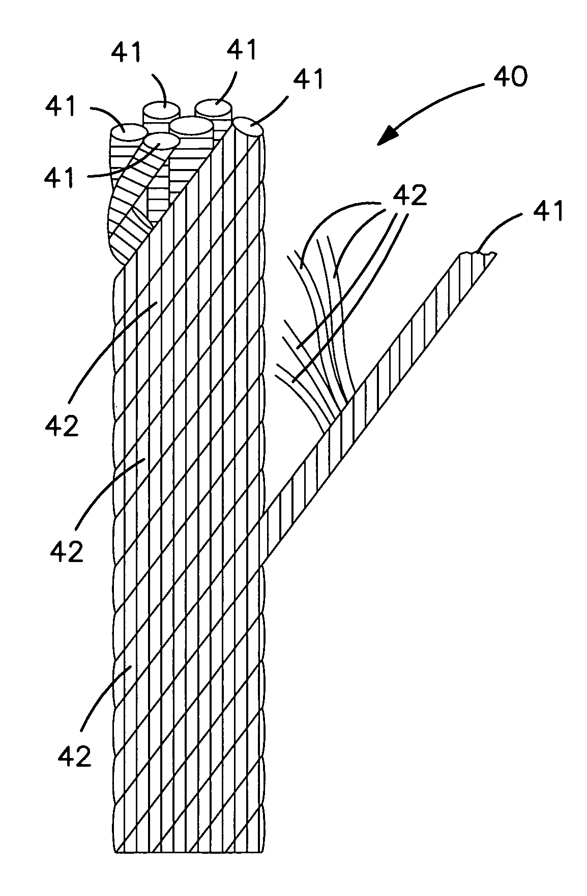
Fluoropolymer fiber composite bundle
a fluoropolymer and fiber bundle technology, applied in the direction of braids, weaving, yarn, etc., can solve the problems of lcp fibers being particularly susceptible to this failure mechanism, reducing the life of ropes, and being subjected to high tensile and bending stresses, so as to achieve high strength fibers, enhance fatigue performance, and high fiber strength
- Summary
- Abstract
- Description
- Claims
- Application Information
AI Technical Summary
Benefits of technology
Problems solved by technology
Method used
Image

Examples
example 1
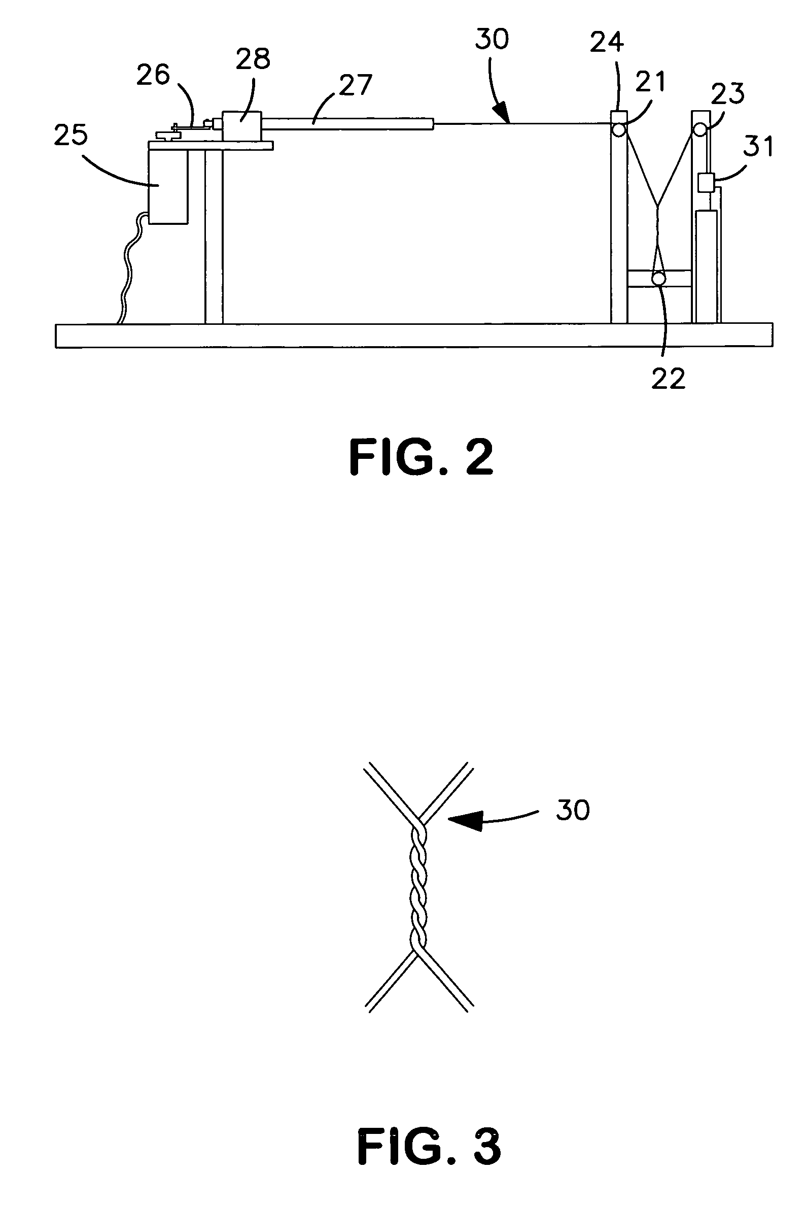
[0074]A single ePTFE fiber was combined with a single liquid crystal polymer (LCP) fiber (Vectran®, Celanese Acetate LLC, Charlotte, N.C.) and subjected to the afore-mentioned abrasion test. The results from this test were compared against the results from the test of a single LCP fiber.
[0075]An ePTFE monofilament fiber was obtained (HT400d Rastex® fiber, W.L. Gore and Associates, Inc., Elkton Md.). This fiber possessed the following properties: 425 d weight per unit length, 2.29 kg break force, 5.38 g / d tenacity and 1.78 g / cc density. The LCP fiber had a weight per unit length of 1567 d, a 34.55 kg break force, and a tenacity of 22.0 g / d.
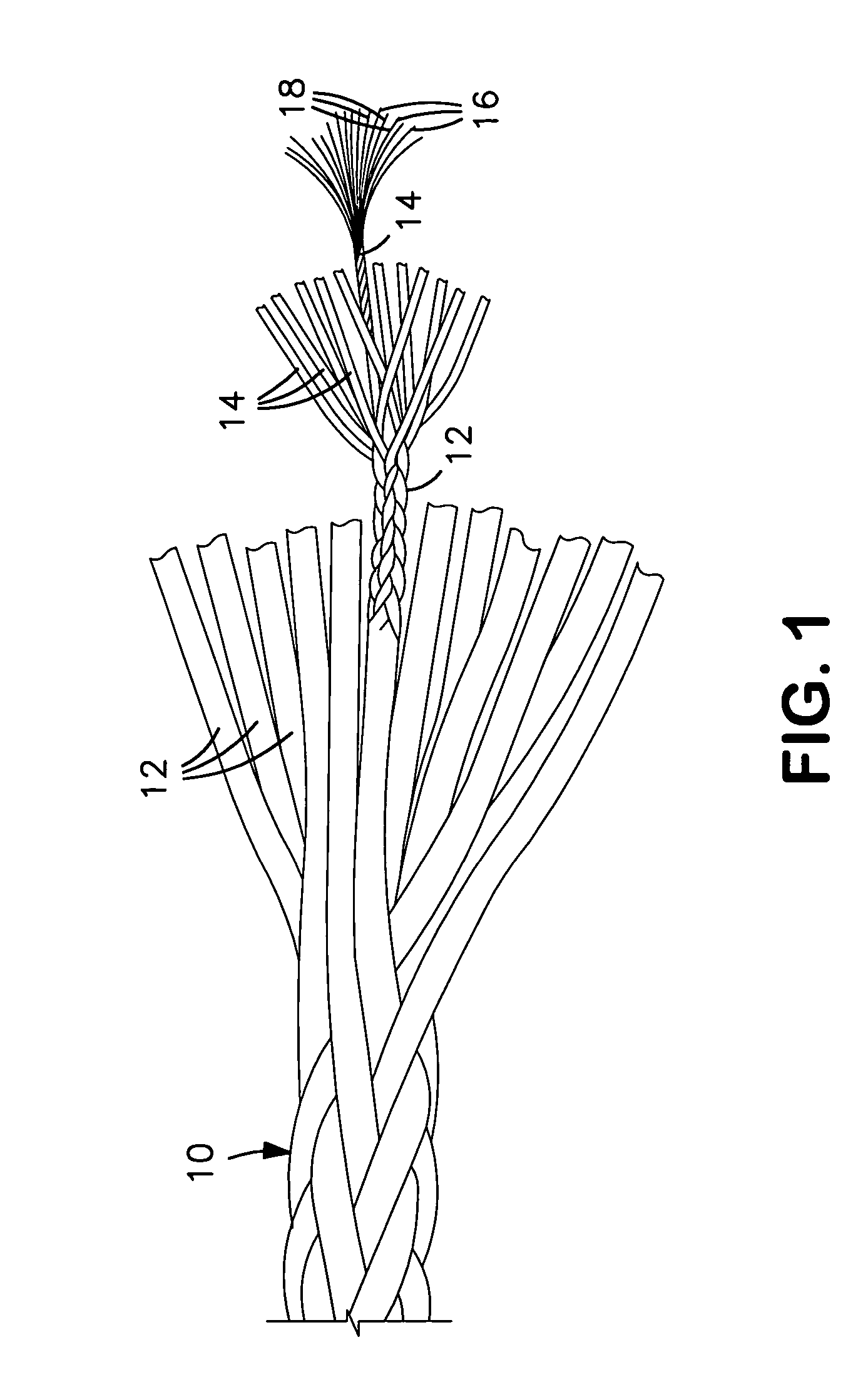
[0076]The two fiber types were combined by simply holding them so that they were adjacent to one another. That is, no twisting or other means of entangling was applied. The weight percentages of these two fibers when combined were 79% LCP and 21% ePTFE. The weight per unit length of the composite bundle was 1992 d. The break force of the composite ...
example 2a
[0083]A single ePTFE monofilament fiber was combined with a single ultra high molecular weight polyethylene (UHMWPE) fiber (Dyneema® fiber, DSM, Geleen, the Netherlands). Abrasion testing was performed as previously described. The composite bundle test results were compared to the results from the test of a single UHMWPE fiber.
[0084]An ePTFE monofilament fiber as made and described in Example 1 was obtained. The two fiber types were combined by simply holding them so that they were adjacent to one another. That is, no twisting or other means of entangling was applied. The weight percentages of these two fibers when combined were 79% UHMWPE and 21% ePTFE. The weights per unit length of the UHMWPE and the composite bundle were 1581 d and 2006 d, respectively. The break forces of the UHMWPE and the composite bundle were 50.80 kg and 51.67 kg, respectively. The tenacities of the UHMWPE and the composite bundle were 32.1 g / d and 25.7 g / d, respectively. Adding the ePTFE fiber to the UHMWP...
example 2b
[0088]A combination of an ePTFE fiber and an UHMWPE fiber was created and tested as described in Example 2a, except that in this case the ePTFE fiber was a multifilament fiber. A 400 d ePTFE monofilament fiber was towed using a pinwheel to create a multifilament ePTFE fiber. The multifilament fiber possessed the following properties: 405 d weight per unit length, 1.18 kg break force, 2.90 g / d tenacity and 0.72 g / cc density.
[0089]One multifilament ePTFE fiber was combined with one UHMWPE fiber as described in Example 2a. The properties and testing results for the UHMWPE fiber are presented in Example 2a. The composite bundle consisted of 80% UHMWPE by weight and 20% ePTFE by weight.
[0090]The weight per unit length of the composite bundle was 1986 d. The break force of the composite bundle was 50.35 kg. The tenacity of the composite bundle was 25.4 g / d. Adding the ePTFE fiber to the UHMWPE fiber changed the weight per unit length, break force, and tenacity by +26%, −1%, and −21%, resp...
PUM
| Property | Measurement | Unit |
|---|---|---|
| length | aaaaa | aaaaa |
| speed | aaaaa | aaaaa |
| gauge length | aaaaa | aaaaa |
Abstract
Description
Claims
Application Information