Manufacturing method of rubber member for tire, and pneumatic tire

A manufacturing method and rubber technology, applied to pneumatic tires, tire parts, tires, etc., can solve problems such as residual air and tire quality deterioration, and achieve high-quality results

Inactive Publication Date: 2007-05-23
SUMITOMO RUBBER IND LTD
View PDF3 Cites 7 Cited by
  • Summary
  • Abstract
  • Description
  • Claims
  • Application Information

AI Technical Summary

Problems solved by technology

Therefore, air tends to remain in the gap (e) after vulcanization molding, and the quality of the tire deteriorates

Method used


Image

  • Manufacturing method of rubber member for tire, and pneumatic tire
  • Manufacturing method of rubber member for tire, and pneumatic tire
  • Manufacturing method of rubber member for tire, and pneumatic tire

Examples


Embodiment Construction

[0021] Embodiments of the invention will be described with reference to illustrated examples.

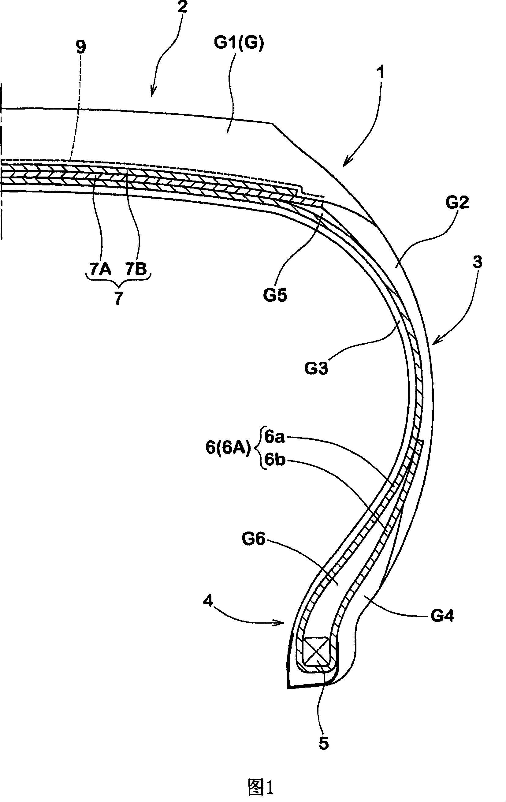
[0022] Fig. 1 is a sectional view showing an example of a pneumatic tire vulcanized using a tire rubber member manufactured by the manufacturing method of the present invention. In FIG. 1, a pneumatic tire 1 includes: a plurality of rubber members G having different rubber components; and a cord reinforcement layer including a carcass 6 forming a skeleton of the tire and a belt 7 arranged radially outside the carcass 6. .

[0023] The carcass 6 includes one or more (one in this example) carcass plies 6A on which carcass cords are arranged at an angle of 70 to 90 degrees with respect to the circumferential direction of the tire. In this example, the carcass ply 6A includes a ply body 6 a extending from the tread portion 2 to the bead core 5 of the bead portion 4 via the sidewall portion 3 , and a ply body 6 a connected to both sides of the ply body 6 a and wound around the carcass. ...


PUM


Abstract

A manufacturing method of a rubber member for a tire includes a winding step in which a rubber strip is spirally winding and overlapping around a surface of a to-be wound body, thereby forming a tire rubber member around which the rubber strip is overlapped. A plurality of air-vent grooves are formed on at least one of surfaces of the rubber strip. Each air-vent groove extends at an angle theta of 20 to 90 DEG with respect to the longitudinal direction of the rubber strip, the maximum groove width of the air-vent groove is 0.3 to 3.0 mm, and the maximum groove depth thereof is 0.1 to 3.0 mm.

Description

technical field [0001] The present invention relates to a manufacturing method of a tire rubber member, which forms a tire rubber member such as tread rubber and sidewall rubber by overlapping and helically winding rubber strips, and also relates to a method of vulcanizing using the above rubber member. Pneumatic tires formed. Background technique [0002] In pneumatic tires, various parts require different characteristics, therefore, pneumatic tires are made of various rubbers with different compositions and cross-sectional shapes such as tread rubber, sidewall rubber, clincher rubber, belt insulation rubber, and inner liner rubber. Components are made. Usually, each rubber member is formed in the green tire forming step in the form of winding a wide extruded product having a desired cross-sectional shape extruded by a rubber extruder once around a forming drum or the like. [0003] In recent years, as shown in FIG. 11A , a so-called tape winding system has been proposed ...

Claims


Application Information

Patent Timeline
IPC IPC(8): B29D30/60B60C5/00
Inventor 坂本雅之
Owner SUMITOMO RUBBER IND LTD
Why Eureka
Try Eureka