Plastic electronic seal technology

An electronic seal, plastic technology, applied in inspection devices, alarms by breaking/disturbing straightened ropes/wires, flexible slender components, etc., can solve the problems of tight monitoring of security products

Inactive Publication Date: 2007-05-23
广州朗昇网络科技有限公司
View PDF0 Cites 3 Cited by
  • Summary
  • Abstract
  • Description
  • Claims
  • Application Information

AI Technical Summary

Problems solved by technology

[0003] In order to improve the lack of sensitivity, real-time and monitoring of electronic seal anti-thef

Method used


Image

  • Plastic electronic seal technology
  • Plastic electronic seal technology

Examples


Embodiment Construction

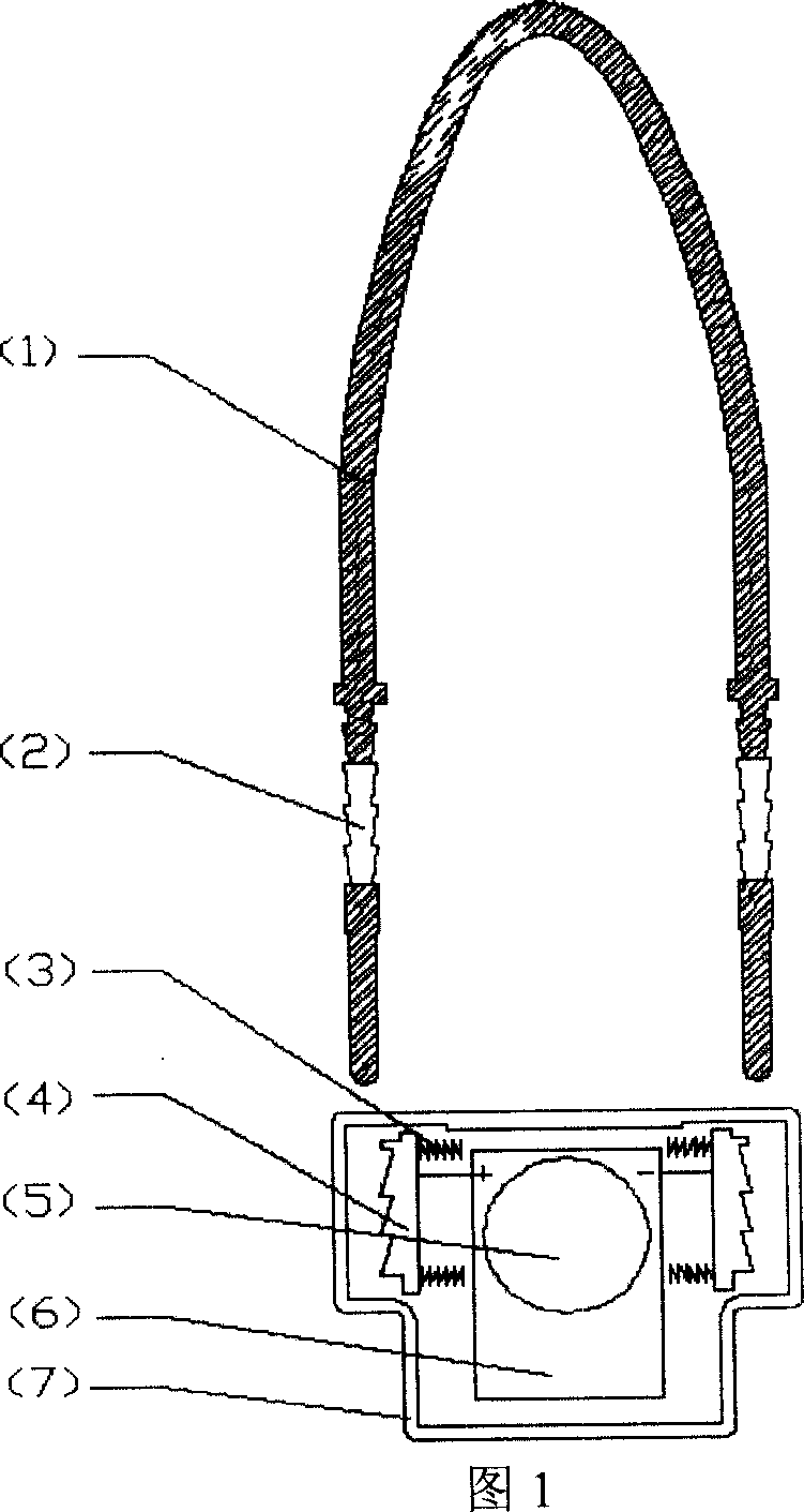
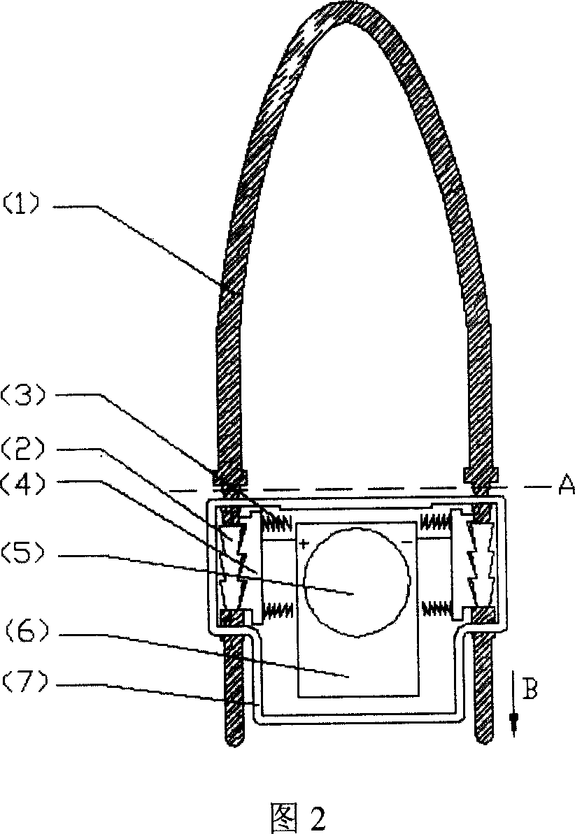
[0010] In the embodiment shown in Figure 1, in the main body (7) of the electronic seal, the spring (3), the rack (4) is in contact with the control element (5), when the rope (1) is introduced into the main body of the electronic seal (7) ) at both ends, the rack (4) compresses the spring (3), and the rope (1) can be smoothly introduced along the direction of the teeth until the exposed conductive part (2) of the rope (1) contacts the rack (4). Due to the effect of the spring (3) and the undercut structure of the exposed conductive part (2) of the rope, the rope (1) is locked and cannot be pulled out directly. At this time, the rope (1) and the control element form an electric circuit through the rack (4), and the detection device in the control element (6) detects that the resistance at both ends of the rope (1) is in a constant state, and the state information is stored in the control element (6). Among the stored data, the stored data can be read by the background system. ...


PUM


Abstract

The invention uses conductive plastic with conductive stuff as electric seal line, wherein when the line is inserted into the main body of electric seal, it will be connected to the connector, spring, tooth bar, controller and battery of electric detector in the main body, to form integral circuit loop; when the line is cut off and drawn outside the electric seal, the former closed loop will be broken. Therefore, by detecting the circuit change of line, it can detect the state of electric seal.

Description

Technical field [0001] The invention uses conductive plastic as the rope material of the electronic seal. When the rope is inserted into the main body of the electronic seal, the rope is connected with the joint, the control element and the battery of the electronic detection device in the main body of the electronic seal to form a complete electrical circuit. Different circuit state changes when opening, identifying the opening and closing state of the electronic seal, judging the legitimacy of the opening state of the electronic seal, and preventing counterfeiting; using PS, PC, ABS, PA, PBT, PPO, polysulfone, polyphenylene ether, poly Conductive plastic products based on PEEK, PPS, Nylon, PE, POM, PP and PC are used as electronic seal rope materials. Background technique [0002] At present, most electronic seals use the on / off detection of the electric circuit (magnetic circuit) inside the seal to judge the opening state of the electronic seal. The rope is inserted into...

Claims


Application Information

Patent Timeline
IPC IPC(8): B65D63/14G07C11/00G08B13/12
Inventor 李新江刘志吉昶
Owner 广州朗昇网络科技有限公司
Why Eureka
Try Eureka