Screw pump and screw gear

A technology of helical gears and helical strips, applied in the field of helical gears, can solve problems such as inability to accommodate helical gears and poor degrees of freedom

Inactive Publication Date: 2007-05-23
TOYOTA IND CORP
View PDF1 Cites 2 Cited by
  • Summary
  • Abstract
  • Description
  • Claims
  • Application Information

AI Technical Summary

Problems solved by technology

However, when the winding start lead angle DegS and the winding end lead angle DegE are changed in order to change the gas compression characteristics of the screw pump, the total length L of the helical gear may not be able to accommodate the screw in the pump chamber. gear value
Therefore, the degree of freedom for changing the gas compression characteristics of the screw pump of Patent Document 1 is poor.

Method used


Image

  • Screw pump and screw gear
  • Screw pump and screw gear
  • Screw pump and screw gear

Examples


Embodiment Construction

[0021] Next, an embodiment of the present invention will be described with reference to FIGS. 1 to 3( b ).

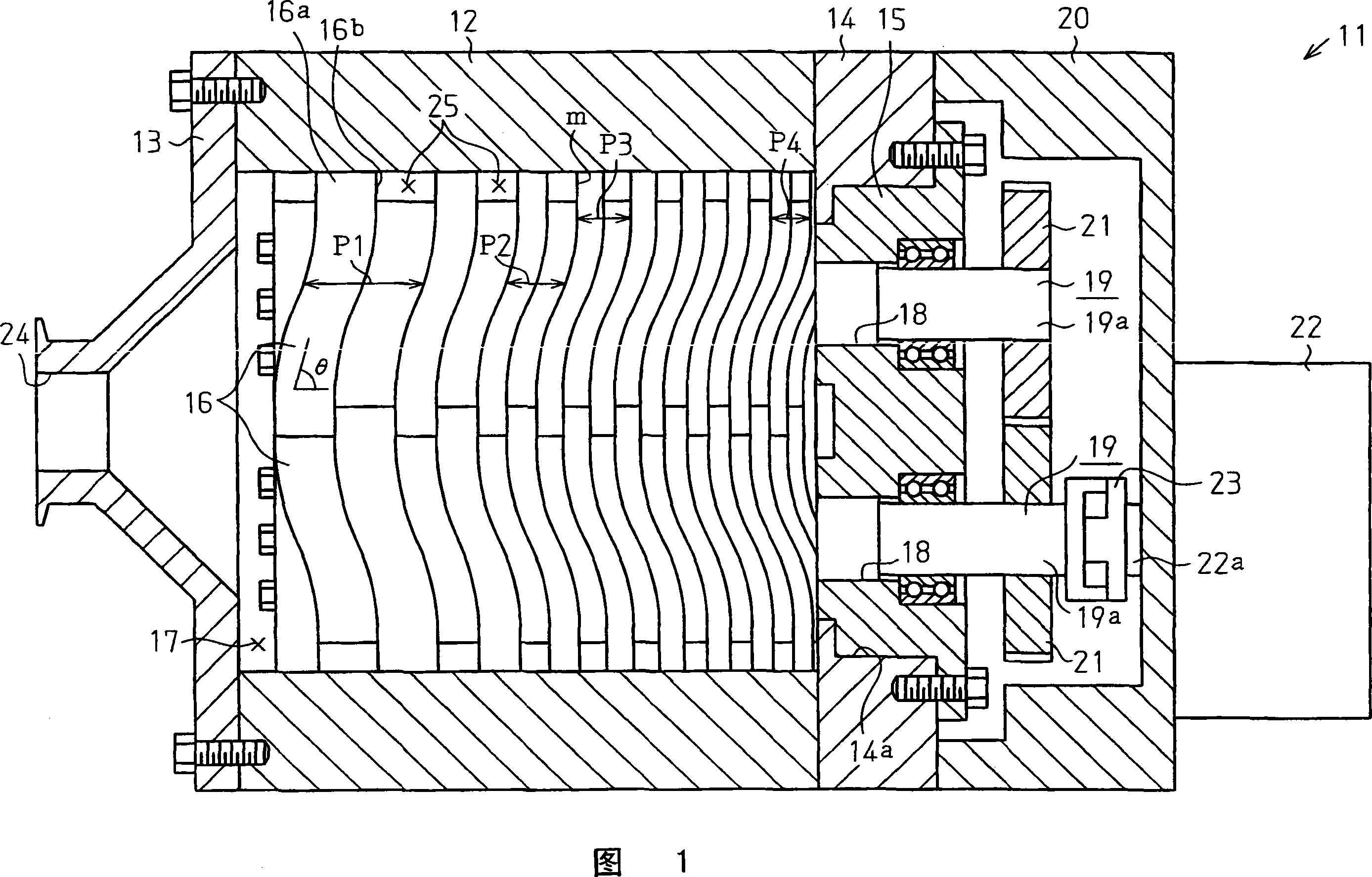
[0022] As shown in FIG. 1 , a screw vacuum pump 11 according to this embodiment has a cylindrical rotor case member 12 and a cover-shaped front case joined to the front end (left side in FIG. 1 ) of the rotor case member 12 . The body member 13 and the plate-shaped rear case member 14 joined to the rear end (right side in FIG. 1 ) of the rotor case member 12 . A stepped mounting hole 14 a is formed in the rear housing member 14 , and the bearing body 15 is fixed to the rear housing member 14 by bolts while being fitted in the mounting hole 14 a. A pair of helical rotors (helical gears) 16 functioning as a fluid conveying body are housed in the rotor case member 12 . A pump chamber 17 is formed between the outer peripheral surface of these screw rotors 16 and the inner peripheral surface of the rotor case member 12 . In addition, the concrete structure of the said scre...


PUM


Abstract

A screw pump is provided with a pair of screw rotors serving as fluid transfer bodies. With respect to a rotation angle (x) around an axis of each of the screw rotors, a change of a lead angle (thelta) from a winding start angle (0), which is the rotation angle (x) corresponding to a leading end of a spiral groove, to a winding end angle (E), which is the rotation angle (x) corresponding to a trailing end of the spiral groove, can be expressed by a lead angle change function (x). The lead angle change function (x) is structured by a combination of a plurality of change functions 1(x) and 2(x) having different manners of changing. It is possible to arbitrarily set a manner in which the lead angle (thelta) changes in accordance with a combination of a plurality of change functions 1(x) and 2(x). Therefore, it is possible to arbitrarily set a fluid compression characteristic of the pump in a relation with an axial length (L) of the screw rotor.

Description

technical field [0001] The present invention relates to a screw pump used, for example, in a semiconductor manufacturing process and a screw gear suitable for use in the screw pump. Background technique [0002] Generally, in a semiconductor manufacturing process, a screw pump is used as a vacuum pump in order to form a vacuum environment. That is, in a semiconductor manufacturing process, in order to perform various processes on a wafer in a vacuum environment, F as a fluid is supplied into a container containing the wafer. 2 Gas and other inert gases, on the other hand, the gas is mixed with the impurities (O 2 , CO 2 etc.) together to form a clean vacuum environment in the container. As such a vacuum pump, a screw pump described in Patent Document 1, for example, is conventionally known. [0003] In the screw pump of Patent Document 1, a pair of helical gears meshing helically, that is, a pair of helical rotors function as a fluid transport body (gas transport body). ...

Claims


Application Information

Patent Timeline
Patent Type & Authority Applications(China)
IPC IPC(8): F04C18/16F04C25/02F04C29/00F04C18/08
CPCF04C18/16F04C18/084Y10T74/1987
Inventor 山本真也藏本觉越坂亮介伊藤英之
Owner TOYOTA IND CORP
Why Eureka
Try Eureka