
Mounts for vehicle parking sensors

A technology for installing devices and sensors, which is applied in the field of parking sensors, can solve problems such as cost increase, delayed vehicle development, and imperfect parking sensor installation devices, and achieve the effect of finishing the seat ring and satisfying the economy

Inactive Publication Date: 2007-05-30
NISSAN MOTOR CO LTD
View PDF0 Cites 10 Cited by
  • Summary
  • Abstract
  • Description
  • Claims
  • Application Information

AI Technical Summary

Problems solved by technology

As a result, the installation must be fine-tuned at a later stage, which leads to increased costs and delays in the development of the vehicle
[0008] Existing parking sensor installations are inadequate at addressing these often conflicting needs

Method used


Image

  • Mounts for vehicle parking sensors
  • Mounts for vehicle parking sensors
  • Mounts for vehicle parking sensors

Examples


Embodiment Construction

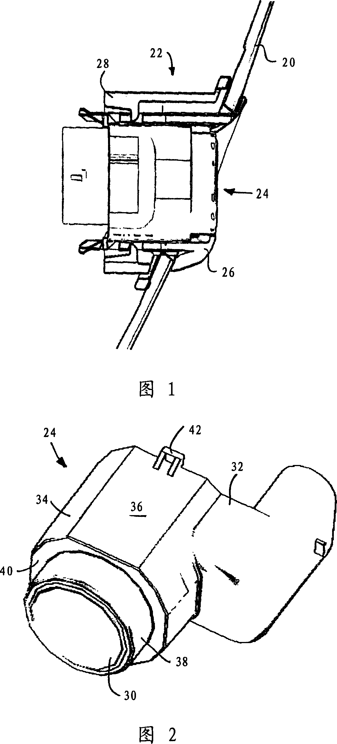
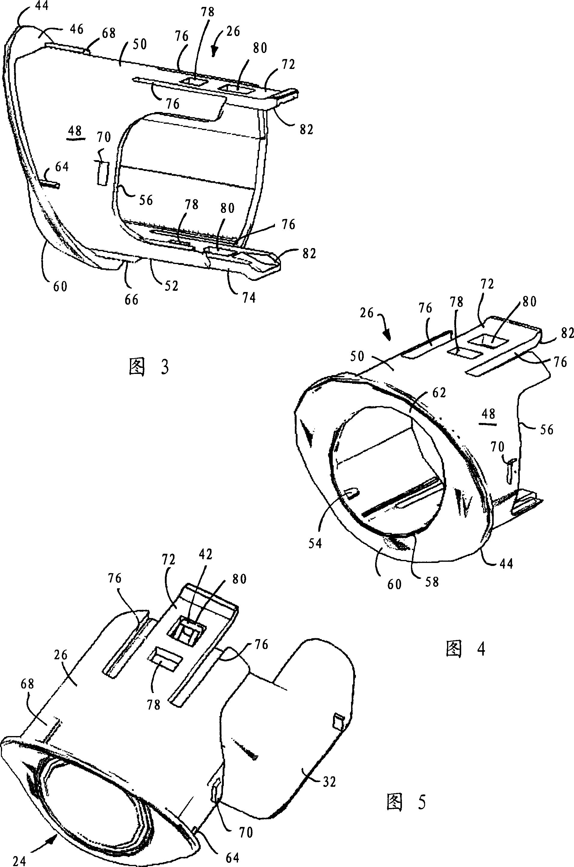
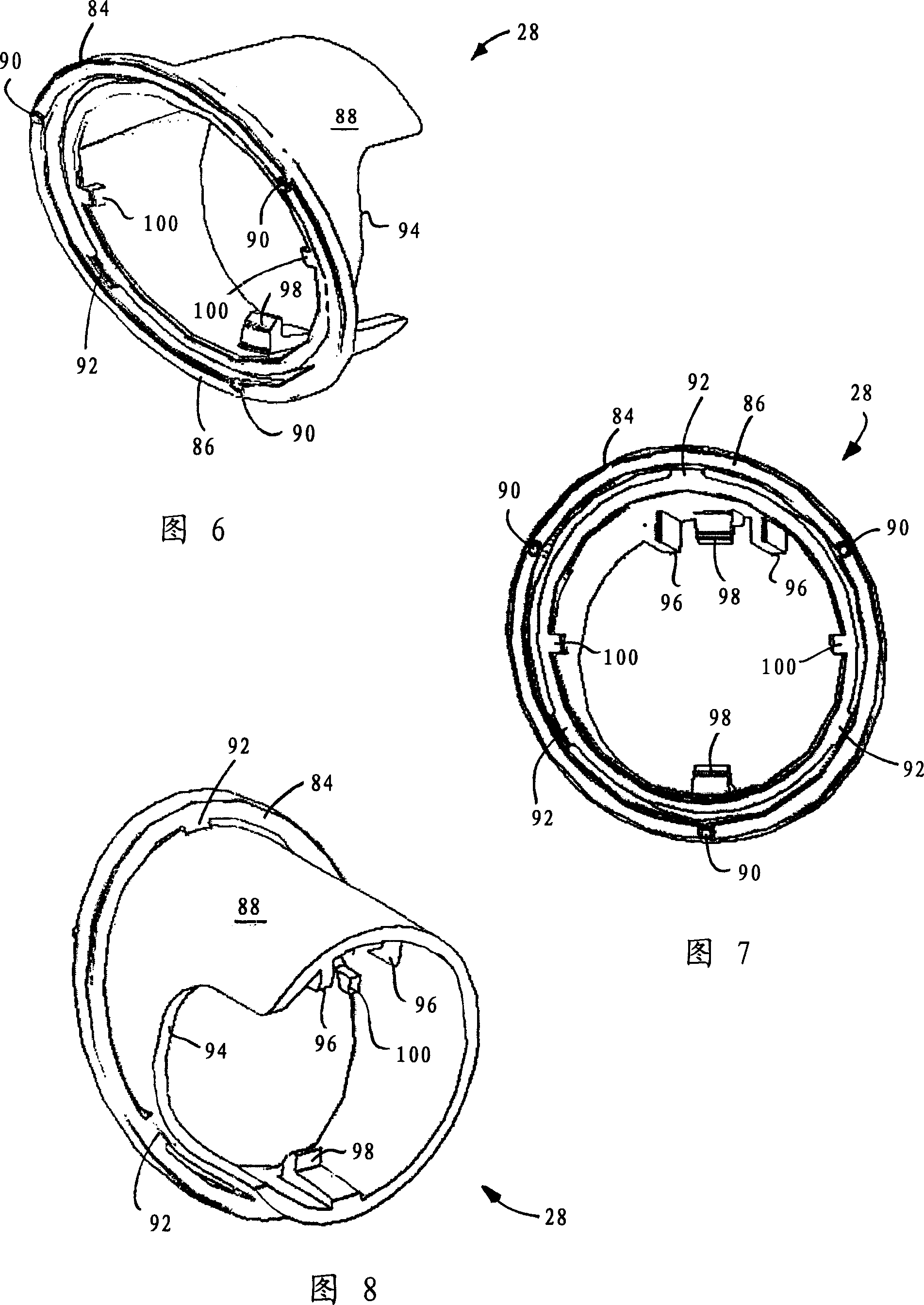
[0035] Referring to Figure 1 of the drawings, a vehicle bumper typically includes an elastically deformable outer layer 20 of molded plastic, such as polypropylene. A hole formed in the bumper skin 20 at the desired sensor location receives a sleeve-like mounting device 22 which in turn serves to hold a sensor 24 . The mounting device 22 includes a generally tubular seat 26 for receiving the sensor 24, and a generally tubular clip 28 engageable with and surrounding the seat 26 to retain the seat 26. In the hole on the bumper skin 20. The central longitudinal axis of sensor 24 is coaxial with race 26 and clip 28 and defines the direction of insertion and assembly of these components.

[0036] The features of sensor 24, race 26 and clip 28 will now be described individually and their interaction collectively.

[0037]Referring first to FIG. 2 , a typical parking sensor 24 is generally cylindrical and extends from a transducer 30 at a proximal end to a connector 32 at a distal ...


PUM


Abstract

A mount for a vehicle parking sensor comprises a bezel for receiving the sensor and a clip engageable with the bezel to retain the bezel at a sensor location on the vehicle. The bezel and the clip each have a respective flange at their proximal end and a body extending distally from the flange. When the clip is engaged with the bezel, the flanges co-operate to embrace the edge of a mounting hole provided in the vehicle at the sensor location. By means of the invention, the flange of the clip is attached to the body of the clip for resilient movement of at least a majority of said flange with respect to said body. Consequently, the mount of the invention is able to accommodate or compensate for variations in the local shape or curvature of a vehicle bumper skin at different locations on a bumper or indeed on different bumpers.

Description

technical field [0001] The invention relates to parking sensors for vehicles and in particular to mounting devices for such sensors. Background technique [0002] It is increasingly common for vehicles to be fitted with parking sensors to aid in maneuvering in confined spaces. Parking sensors, also called parking distance sensors or simply parking aids, usually work on the principle of sound waves. Each sensor acts as a transceiver for transmitting and receiving acoustic energy at a different ultrasonic frequency. When the reflected acoustic energy indicates that the vehicle is approaching an obstacle, the driver receives an audible and / or visual warning in the vehicle. The alarm typically indicates the proximity of the obstacle, for example by changing the frequency of the sound of the warning, such as a beep. The alert may also indicate the location of the obstacle relative to the vehicle, for example via a variable visual display. [0003] Parking sensors are typicall...

Claims


Application Information

Patent Timeline
IPC IPC(8): B60R16/02G01S15/93B60R19/48
CPCB60R19/483G10K11/004
Inventor 阿利斯泰尔·布朗
Owner NISSAN MOTOR CO LTD
Learn More