

Anti-poking lock
An anti-pickling and lock head technology, which is applied in the field of pin locks, can solve the problems of being easy to be opened technically by unlocking tools and the poor anti-pickling ability of pin locks, etc., so as to prevent the opening and increase the difficulty
- Summary
- Abstract
- Description
- Claims
- Application Information
AI Technical Summary
Problems solved by technology
Method used
Image

Examples
Embodiment 1
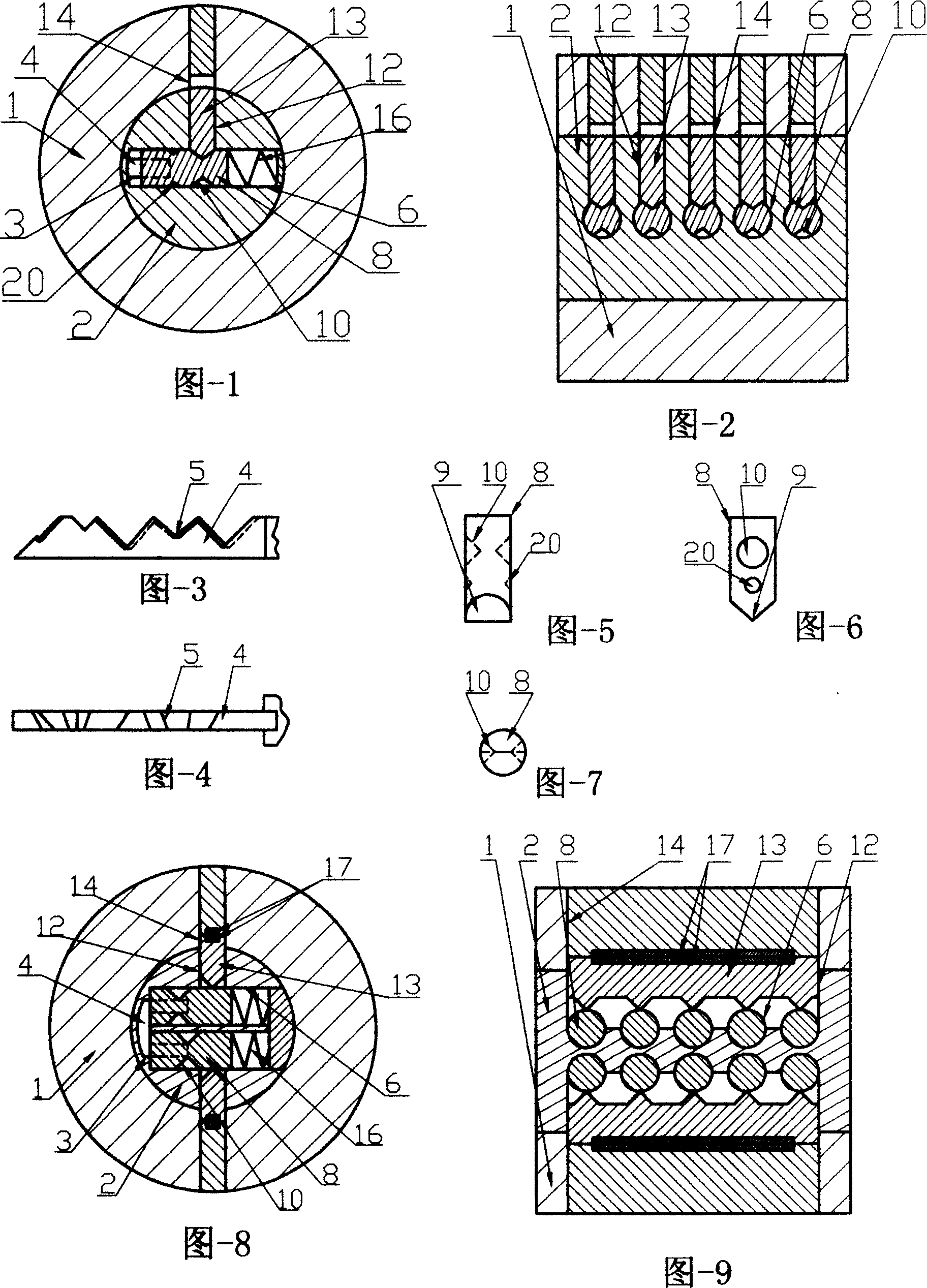
[0038] Embodiment 1: An anti-dialing lock with a single row of angle pins, the structure of which is shown in Figure 1 to Figure 7 . A rotatable lock core (2) is arranged in the lock head (1), and the key hole (3) in the lock core (2) communicates with the pin hole (6). A row of pinholes (6) in the lock core (2) communicate with the corresponding circular side pinholes (12) and the circular lock pinholes (14) on one side, and there are pinholes in each pinhole (6). Its head (9) of an angle marble (8) is in the shape of an ax and matches the oblique teeth flower (5) of the key (4), and each angle marble (8) has a pair of side walls on different heights and angle positions. Relative circle pit breach (10), each angle pin shot from a slingshot (8) back has spring (16). All have a cylindrical side pin (13) in each circular side pin hole (12), the breach (10) of its head and angle pin (8) sidewall cooperates, and length is equal to from breach (10) to lock. The distance of the ou...
Embodiment 2
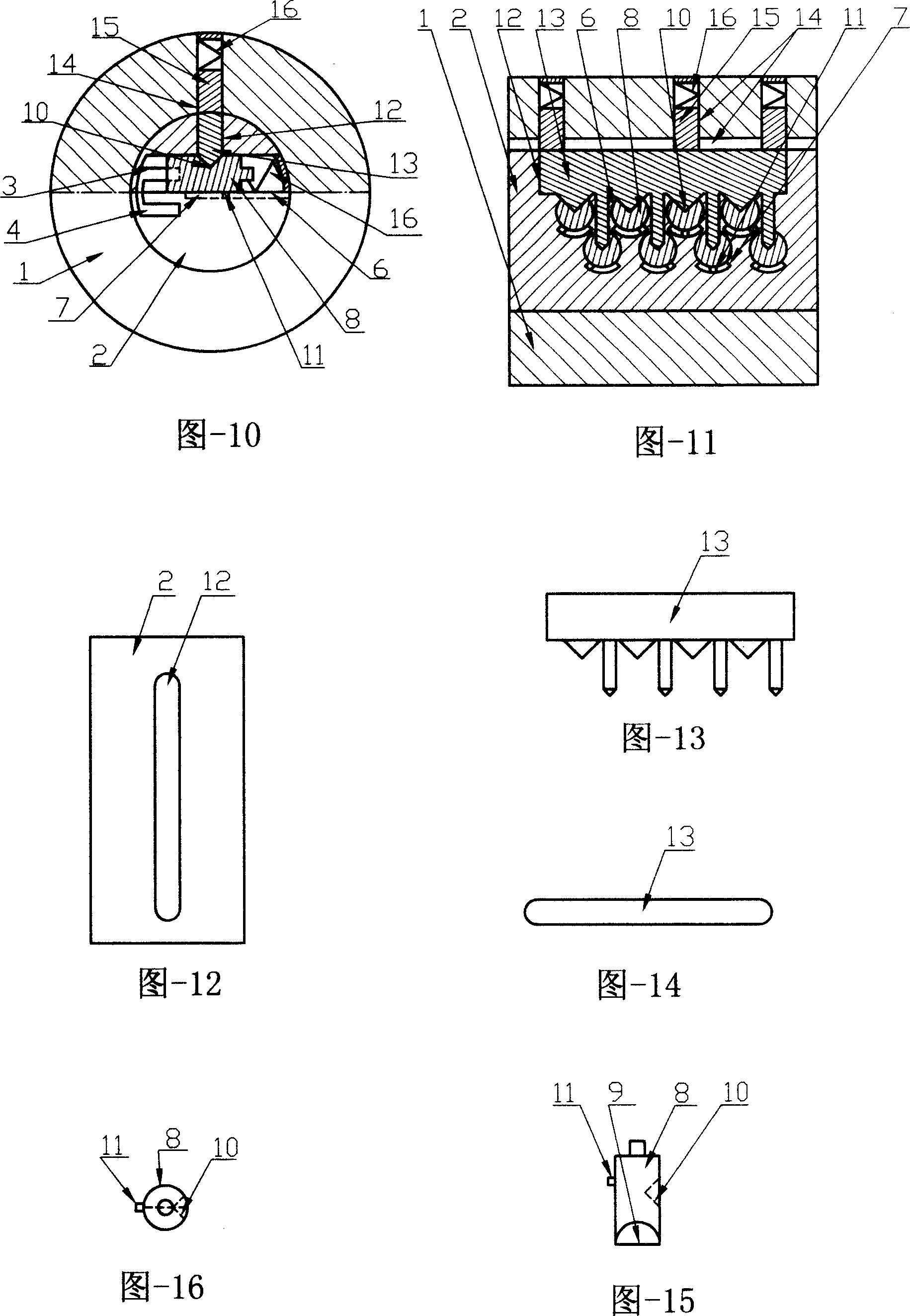
[0044] Embodiment 2: An anti-dialing lock with two rows of restricted angle pins arranged in a staggered manner and using a spring as the pin pressure. Its structure is shown in Figure 10 to Figure 16 . Contrasted with embodiment one, its difference is that the original row is changed into two rows of staggered pinholes (6) with angled pinholes (8) in it, and the two rows of pinholes (6) are all offset from one side of the same side. The elongated side marble hole (12) communicates with the lock end pin hole groove (14). There is an elongated comb tooth side slingshot (13) in the through hole, and its head comb teeth are matched with respective corresponding angle slingshots (8) side wall gaps (10). Each marble hole (6) has a limit hole (7) on the other side, and each angle pin (8) has a corresponding limit boss (11) on the same side. All have a spring (16) in each pin hole (6), all have a pin pin (15), spring (16) in each pin pin hole (14), and there are two rows of teeth fl...
Embodiment 3
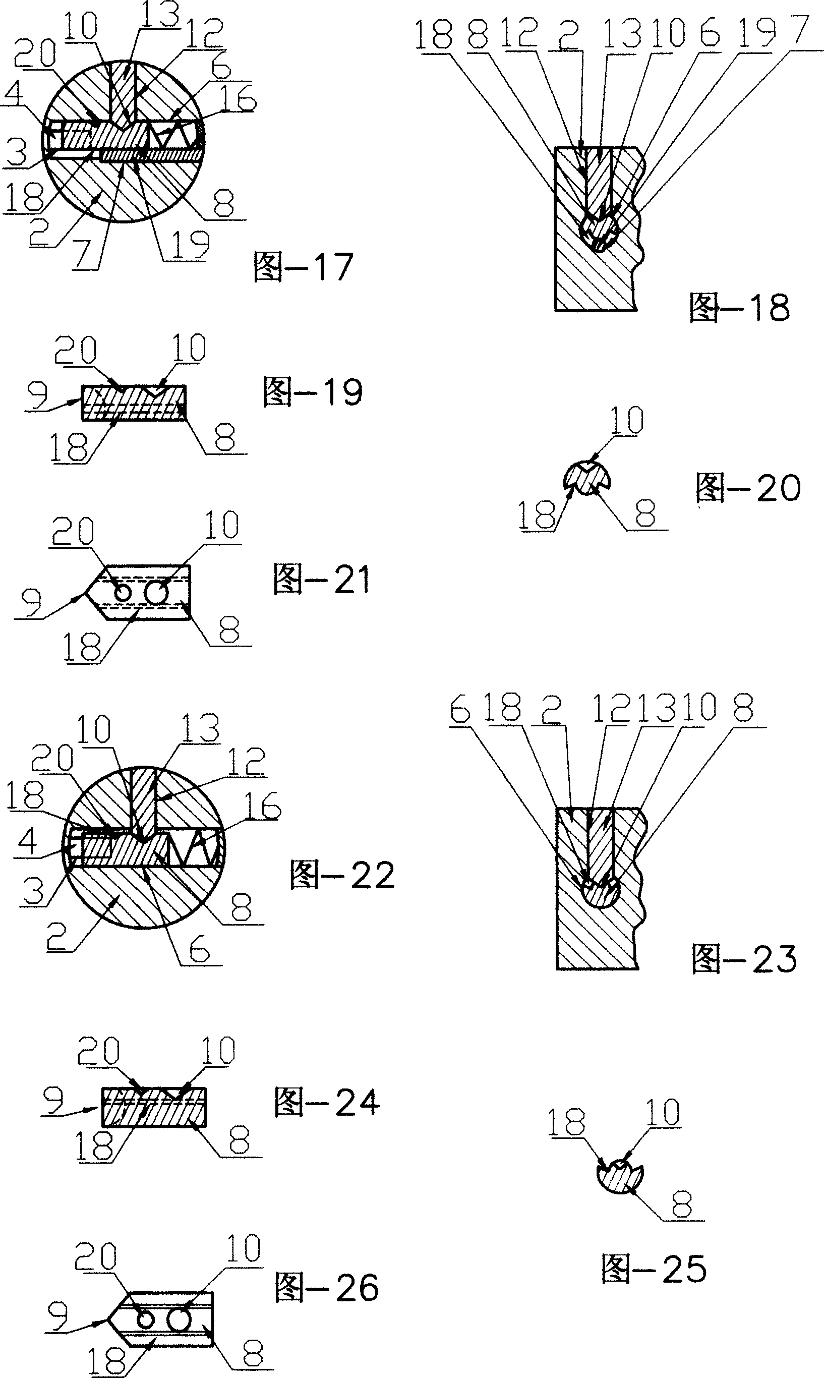
[0045] Embodiment 3: An anti-dialing lock with two rows of angle pins arranged side by side, using magnets as the pressure of the side pins. Its structure is shown in Figure 8 and Figure 9 . Contrasted with embodiment one, its difference is changed from one row to two rows of juxtaposed pinholes (6) with angled pinholes (8) in it, and the two rows of pinholes (6) are respectively connected to one of the pinholes on each side. The long side pinholes (12) and the long pin pin holes (14) are connected. Each convex tooth of its head is matched with the notch (10) of the side wall of the corresponding angle marble (8) respectively, and its tail is matched with the elongated lock end in the two through holes respectively. There is a pair of magnets (17) that are disassembled at the rear portion of the marble hole (14), and springs (16) are arranged at each angle marble (8) afterbody, and two rows of teeth are arranged side by side on the key (4).
[0046]The present invention is no...
PUM
 Abstract
Description
Claims
Application Information