

Plate-fin heat exchanger
A plate-fin heat exchanger and heat exchanger technology, applied in the field of plate-fin heat exchangers, can solve the problems affecting the cooling of hot and humid air in the pre-cooling section, the heat exchanger has a large weight and volume, and achieves flow High speed, compact structure, large volume effect
- Summary
- Abstract
- Description
- Claims
- Application Information
AI Technical Summary
Problems solved by technology
Method used
Image

Examples
Embodiment Construction
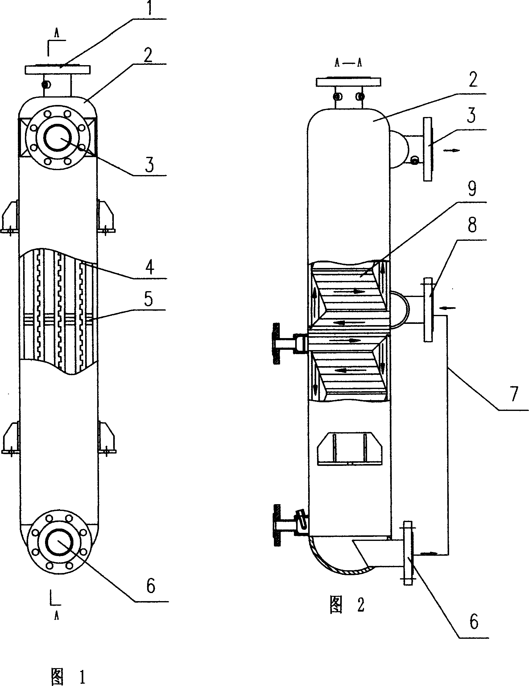
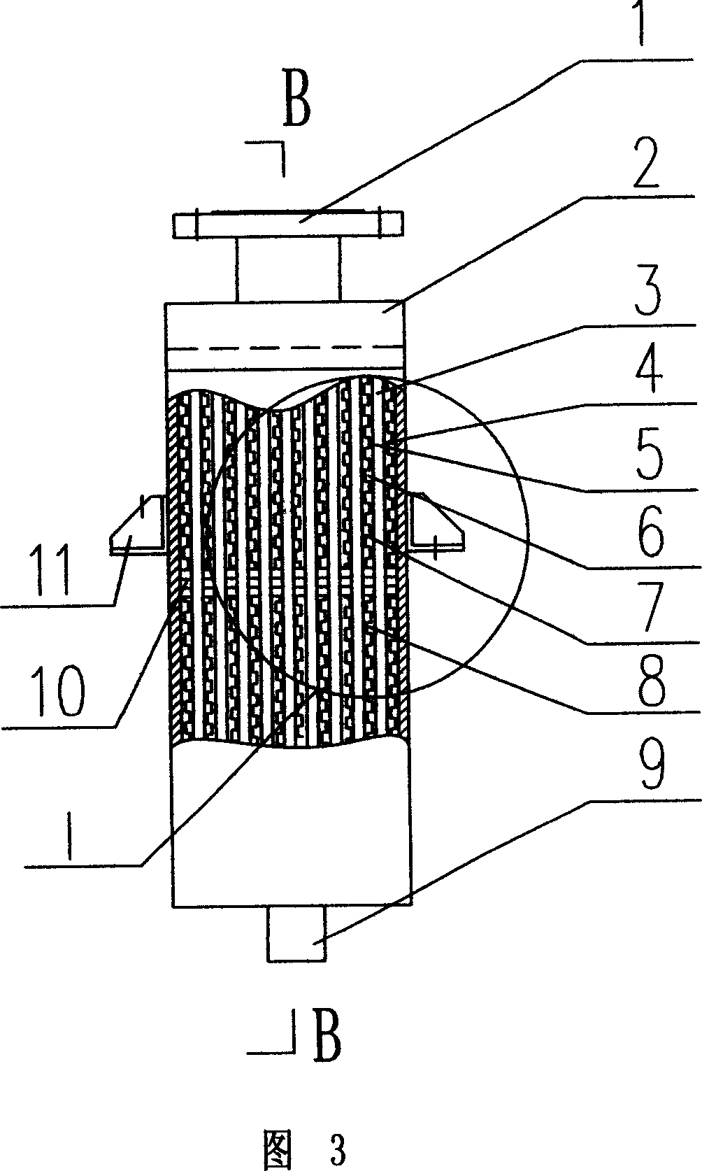
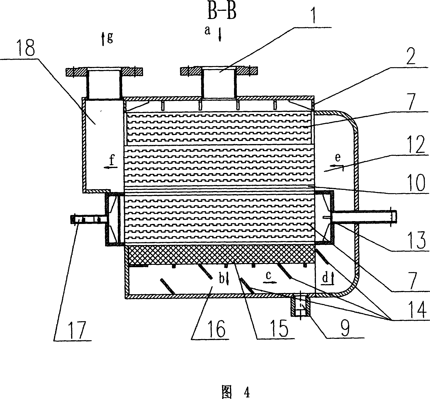
[0013] See Fig. 3, Fig. 4, Fig. 5, Fig. 6, the present invention comprises shell 2 and pre-cooling section and evaporation section distributed in the shell, pre-cooling section and evaporating section respectively comprise cold source channel structure and hot air channel structure, pre-cooling section The hot air channel structure of the cold section is connected to the hot air channel structure of the evaporating section, and the cold source channel structure of the precooling section is separated from the cold source channel structure of the evaporating section by a partition 10, above the precooling section and Below the evaporating section, the shell 2 is provided with an air inlet 1 and a drainage structure respectively. The precooling section and the evaporating section are distributed as a whole on the upper side of the inner space of the shell 2. The bottom and one side of the inner space of the shell 2 are hollow, as shown in Figure 4 On the right side, the air in the...
PUM
 Abstract
Description
Claims
Application Information