Cascaded stack with gas flow recycle in the first stage

一种再循环、再循环系统的技术,应用在电气元件、燃料电池、燃料电池分组等方向,能够解决性能劣化等问题

Inactive Publication Date: 2007-05-30
GM GLOBAL TECH OPERATIONS LLC
View PDF26 Cites 8 Cited by
  • Summary
  • Abstract
  • Description
  • Claims
  • Application Information

AI Technical Summary

Problems solved by technology

However, it is recommended that the feed gas be oxidizing and dry, which can lead to performance degradation at both gas inlets

Method used


Image

  • Cascaded stack with gas flow recycle in the first stage
  • Cascaded stack with gas flow recycle in the first stage
  • Cascaded stack with gas flow recycle in the first stage

Examples


Embodiment Construction

[0020] The following description of the preferred embodiments is merely exemplary in nature and is not intended to limit the invention, its application, or uses.

[0021] As used herein, the term "fluid" means any gaseous and / or liquid material such as, but not limited to, liquid water, water vapor, and combinations thereof.

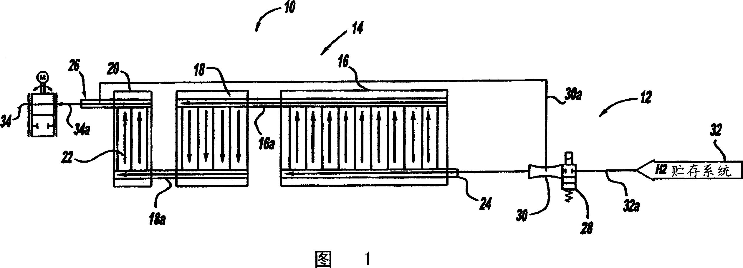
[0022] Referring to FIG. 1, a schematic diagram of a three-stack fuel cell system 10 having a humidification / gas recirculation system 12 operative with respect to the anode flow 14 side of the stack is shown in accordance with one embodiment of the present invention.

[0023] The fuel cell system 10 includes three respective fuel cell stacks 16, 18, 20 in fluid communication with each other, or at least with adjacent fuel cell stacks. The fuel cell stacks 16 , 18 , 20 each contain a plurality of individual fuel cell elements 22 . The number of fuel cell elements 22 in the fuel cell stacks 16, 18, 20, respectively, may vary. Conduit 16a and 18a are prov...


PUM


Abstract

A fuel cell system including a humidification system is described. The humidification system employs a recycling system that recycles relatively humid gas exhausted from a multistage fuel cell stack, either on the anode and / or cathode side, and sends this relatively humid gas back to be combined with relatively dry supply gas, such as but not limited to hydrogen and / or air. The humidified supply gas mixture is then reintroduced into the first stage of the multistage fuel cell stack. A recirculation device, such as but not limited to a pump and / or an ejector, can be used to aid in moving the humid exhaust gas back through a recycle gas line to be combined with the supply gas.

Description

technical field [0001] The present invention relates generally to fuel cell systems, and more particularly to new and improved gas flow recirculation systems for fuel cell systems. Background technique [0002] Fuel cells have been used as power sources in a variety of applications. For example, it has been proposed to use a fuel cell as a power plant in an electric vehicle instead of an internal combustion engine. In a PEM type fuel cell, hydrogen gas is supplied to the anode of the fuel cell and oxygen as an oxidant is supplied to the cathode. A PEM fuel cell includes a membrane electrode assembly (MEA) containing a thin, proton-transporting, non-conductive solid polymer electrolyte membrane with an anode catalyst on one side of the electrolyte membrane and a cathode catalyst on the opposite side. The MEA is sandwiched between a pair of conductive elements, sometimes referred to as gas diffusion media components, which: (1) serve as current collectors for the anode and c...

Claims


Application Information

Patent Timeline
Patent Type & Authority Applications(China)
IPC IPC(8): H01M8/04H01M8/24H01M8/00
CPCH01M8/04097H01M8/249Y02E60/50H01M8/04141
Inventor R·森纳
Owner GM GLOBAL TECH OPERATIONS LLC
Why Eureka
Try Eureka