
Ethernet cache exchanging and scheduling method and apparatus

An Ethernet and cache unit technology, applied in the field of network switching, can solve the problems of delay jitter, large cache overhead, etc., and achieve the effect of reducing cache overhead and flexible scheduling

Inactive Publication Date: 2007-05-30
WUHAN FIBERHOME NETWORKS
View PDF0 Cites 35 Cited by
  • Summary
  • Abstract
  • Description
  • Claims
  • Application Information

AI Technical Summary

Problems solved by technology

[0009] Aiming at the problems in the prior art that the cache overhead of store-and-forward mode is large during high-speed transmission, and the time delay jitter occurs during packet-based queue scheduling, the present invention proposes a high-speed transmission based on Ethernet switching buffer and scheduling method for fixed-length cells and Ethernet switching buffer and scheduling device

Method used


Image

  • Ethernet cache exchanging and scheduling method and apparatus
  • Ethernet cache exchanging and scheduling method and apparatus
  • Ethernet cache exchanging and scheduling method and apparatus

Examples


Embodiment Construction

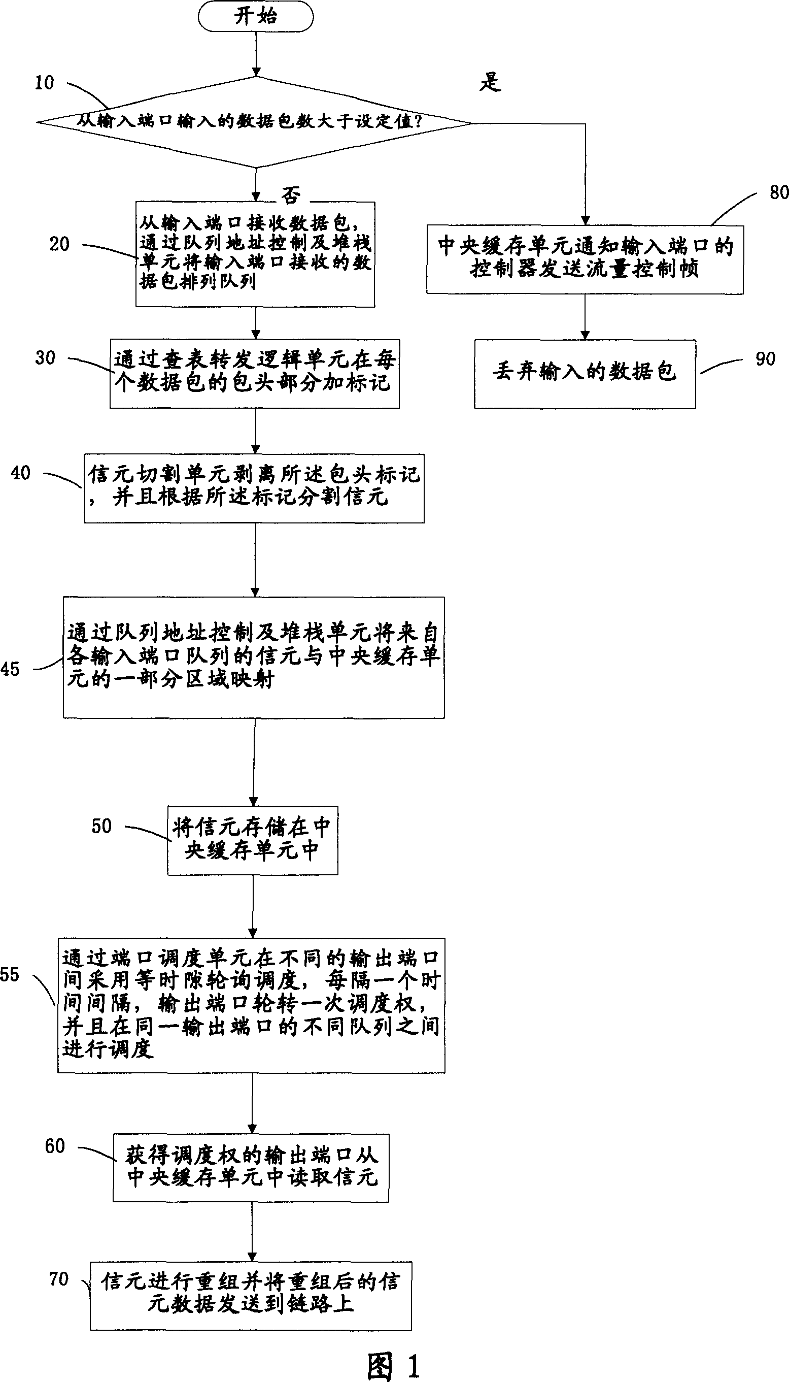
[0027] Fig. 1 is a flow chart of the Ethernet switching cache and scheduling method according to the present invention. According to the Ethernet switching cache and scheduling method provided by the present invention, first, in step 10, the flow of the input port is monitored, and the operation on the data packet is determined according to the monitoring result, for example, receiving the data packet or discarding the data packet.

[0028] When the number of data packets input from the input port is greater than the set value, at step 80 , the central buffer unit will notify the controller of the input port to send a flow control frame, and at step 90 , discard the input data packets.

[0029] When the number of data packets input from the input port is less than the set value, at step 20, the data packets are received from the input port, and the input port may be 12 Gigabit ports, PCI ports and 10 Gigabit ports. The data packet from the input port is arranged in the queue b...


PUM


Abstract

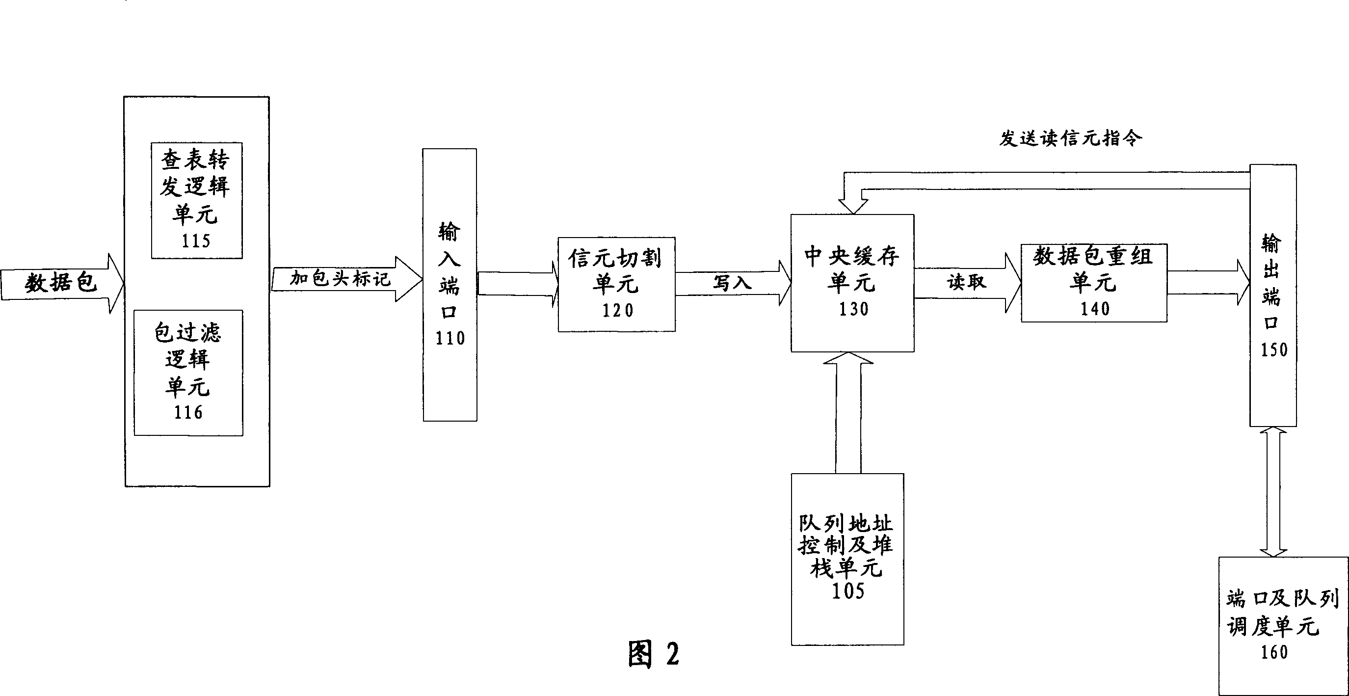
This invention provides one Ethernet exchange buffer and transfer method, which comprises the following steps: receiving data pack from input end; cutting data pack into certain length signal element by cut unit; storing signal element into central memory unit; adopting equal time lag transfer through end and line transfer unit and turning output end by each time lag; adopting run require or transfer of different lines at one output end; after getting transfer, reading signal element from common central buffer unit and the data pack resets the signal element sent to the linkage. This invention also provides one Ethernet exchange buffer and transfer device.

Description

technical field [0001] The invention relates to a network switching method, in particular to a method and device for Ethernet switching cache and scheduling. Background technique [0002] At present, Ethernet switching technologies mainly include cut-through mode and store-and-forward mode. [0003] The Ethernet switching technology of the straight-through mode can be realized by a matrix switch between each Ethernet port. When the matrix switch detects a data packet at the input port, the matrix switch checks the packet header of the data packet, obtains the destination address of the data packet, converts the destination address into a corresponding output port by the dynamic lookup table inside the matrix switch, and Send the data packet directly to the corresponding port to realize the switching function. [0004] Since packets are not stored, the cut-through method has very low latency and very fast switching. But its disadvantages are: because the content of the dat...

Claims


Application Information

Patent Timeline
IPC IPC(8): H04L12/56H04L12/863
Inventor 范其蓬
Owner WUHAN FIBERHOME NETWORKS
Learn More