Broadband patch antenna

A patch antenna, broadband technology, applied in the direction of antenna, slot antenna, resonant antenna, etc., can solve complex antenna structure and other problems

Inactive Publication Date: 2007-05-30
HUBERSUHNER AG
View PDF0 Cites 0 Cited by
  • Summary
  • Abstract
  • Description
  • Claims
  • Application Information

AI Technical Summary

Problems solved by technology

Some solutions proposed for this purpose are described and discussed in the introductory part (column 1-column 3) of the document mentioned at the beginning, but lead to relatively complex antenna structures and do not fully satisfy the requirements for bandwidth requirements

Method used


Image

  • Broadband patch antenna
  • Broadband patch antenna
  • Broadband patch antenna

Examples


Embodiment Construction

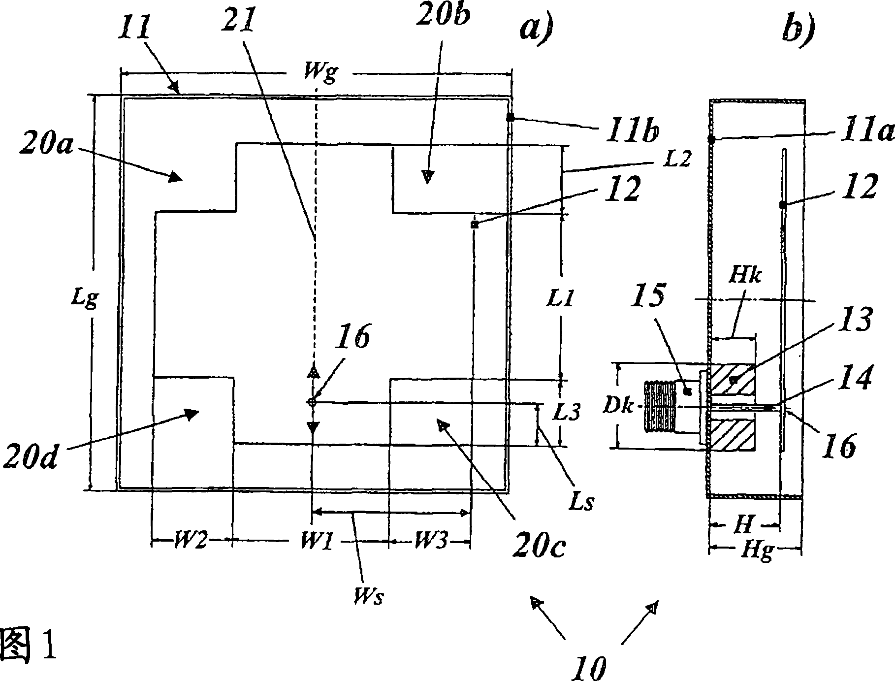
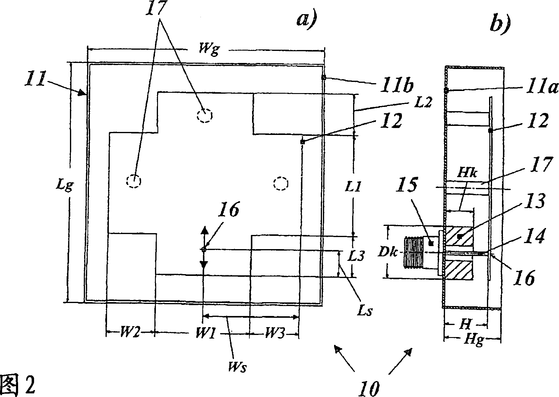
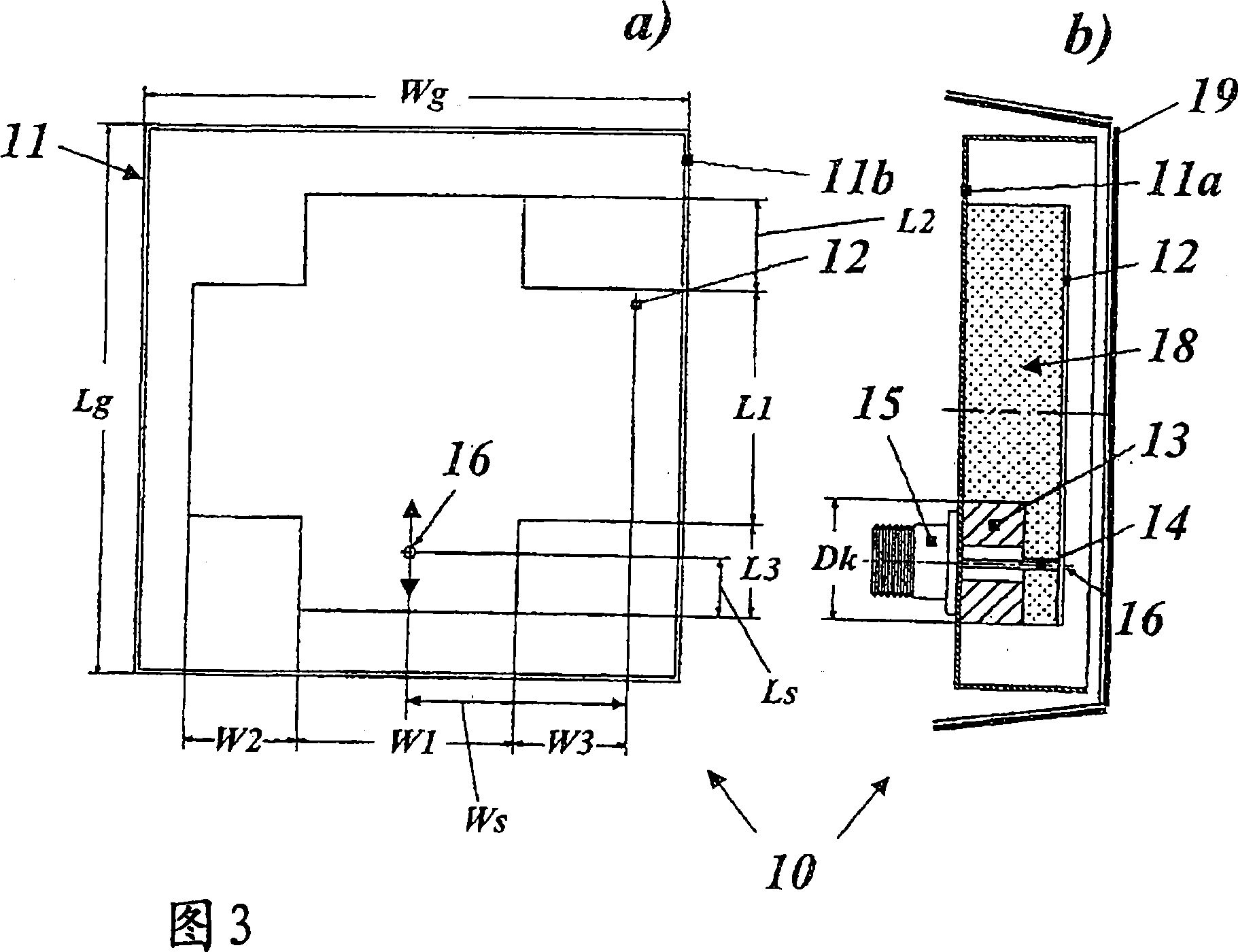
[0021] Fig. 1 shows a top view (Fig. 1a) and a cross-sectional view (Fig. 1b) of a first preferred exemplary embodiment of a broadband patch antenna according to the invention. The broadband patch antenna 10 mainly includes a box-shaped reflector 11 with an opening on one side, a patch plate 12 disposed inside the reflector 11 and having a feeding point 16, and coaxial feeding devices 13, 14, 15, by means of which, RF power can be delivered to patch board 12 from the outside.

[0022] The conductive reflector 11 has a rectangular, planar base 11a having a width Wg and a length Lg. In the exemplary embodiment shown, the base surface 11a is square (Wg=Lg). At the sides, the base area merges into vertical side walls 11b, wherein the side walls 11b have a uniform height Hg. Parallel to the base surface 11a, a planar patch plate 12 is arranged at a height H on the base surface 11a and parallel thereto. The base surface 11a of the reflector 11 is larger than the area of ​​the pat...


PUM


Abstract

Disclosed is a broadband patch antenna (10) comprising a planar metallic patch sheet (12) that is provided with right-angled edges and is disposed at a predetermined first height (H) above and parallel to the planar base area (11a) of an electrically conducting reflector (11), and a device (13, .., 16) for feeding an HF signal into the metallic patch sheet (12). Said feeding device (13, .., 16) encompasses a conductor (14) which is guided in a vertical direction and in an insulated manner through the base area (11a) of the reflector (11) while ending at a feeding point (16) on the metallic patch sheet (12). In order to substantially improve the broadband range while keeping the structure of the antenna simple, the metallic patch sheet (12) has the shape of a cross while the conductor of the feeding device (13,..,16) is configured between the base area (11a) of the reflector (11) and the metallic patch sheet (12) as an inner conductor (14) of a coaxial conductor arrangement.

Description

technical field [0001] The present invention relates to the technical field of antennas, more specifically the invention relates to a broadband patch antenna according to the preamble of claim 1 . [0002] Such an antenna is disclosed, for example, in document US-B1-6,317,084. Background technique [0003] The application of wireless communication technology has developed extremely rapidly in the past two decades. Today, this technology has enabled voice traffic and data traffic to be transmitted in different frequency bands. Basically, the 400, 800, 900, 1800 and 1900MHz bands are used for mobile voice transmission all over the world. With the advent of the UMTS standard (Universal Mobile Telecommunications System), the frequency range has been extended to 2170 MHz. As an alternative to landline telephones - keyword WLL (Wireless Local Loop) - the frequency range between 3400 and 3600 MHz has been issued in several European countries in previous years. If high data rate...

Claims


Application Information

Patent Timeline
Patent Type & Authority Applications(China)
IPC IPC(8): H01Q9/04H01Q5/00H01Q13/18H01Q5/50
CPCH01Q5/0093H01Q13/18H01Q9/0407H01Q9/0442H01Q5/50
Inventor 沃尔夫冈·海德
Owner HUBERSUHNER AG
Why Eureka
Try Eureka