Built-in oblique leg rigid-frame prestress concrete variable cross-section box girder bridge and construction method thereof

A variable-section, pre-stressed technology, used in the erection/assembly of bridges, bridges, bridge materials, etc., can solve the problems of increasing self-weight, main tensile stress cracks in web 2, large downward radial force, etc., to achieve simplification Effects of structural design and construction, small shrinkage creep deflection, and enhanced shear resistance

Inactive Publication Date: 2007-06-06
CHONGQING JIAOTONG UNIVERSITY +1
View PDF0 Cites 14 Cited by
  • Summary
  • Abstract
  • Description
  • Claims
  • Application Information

AI Technical Summary

Problems solved by technology

The thickening of web 2 and bottom plate 1 can solve the problem of pressure bearing, but the contribution to the stiffness of the beam body does not increase the beam height. After increasing the beam height, the stability of web 2 will decrease. Web 2 can be thickened, but further increase Large self-weight, increase the beam height, and the downward radial force of the positive moment bundle in the middle of the span is further increased. Therefore, in the existing technology, the large-span prestressed concrete variable-section box girder bridge increases the span by increasing the girder height of the traditional box chamber structure. , thickened web 2 and bottom plate 1 have relatively large negative effects
[0005] (2) The downward radial force of the floor cable 5 generates shear force along the bridge direction at the corresponding floor position. The bottom plate 1 in the mid-span is relatively thin, generally 25-40 cm. The transverse reinforcement is configured according to the structure. If the axial force is too large, it will easily lead to shear cracks along the bridge direction in the bottom plate 1 of the middle span, and seriously cause the bridge bottom plate 1 to crack and fail.
[0006] (3) The downward radial force of the floor cable 5 directly leads to the tension of the web 2 in the corresponding section, which can easily lead to the main tensile stress cracks in the web 2. Usually, such defects are more common in the range from L / 4 section to L / 2 section , related to this, generally the beam height from L / 4 section to L / 2 section is small, and it is difficult to control the vertical prestress. If the vertical prestress is unreliable, the disease will be aggravated
[0007] (4) Since the floor cable 5 needs to be anchored at the junction of the web 2 and the bottom plate 1 due to structural requirements to shorten the force transmission route, the anchorage area of ​​the floor cable 5 of a long-span bridge is usually from near the mid-span to near the L / 8 section, which is large The positive bending moment area of ​​the variable cross-section box girder bridge constructed by the cantilever pouring method is usually between the L / 4 section and the mid-span L / 2 section. The mid-span L / 2 section is the largest, and the positive bending moment near the L / 8 section is generally small. Or negative bending moment, in order to ensure the force of positive bending moment in the mid-span and the needs of anchoring structure, the floor cable 5 arranged between the L / 4 section and the L / 8 section is unfavorable to the force of this section, and the L / 4 section to L / 8 section The cross-section beam is tall, the eccentricity is large, and the downward radial force is the largest, so the negative effect is large
[0008] (5) The downward radial force of the floor cable 5 directly leads to the mid-span deflection
[0009] (6) The positioning of the arched floor cable 5 is difficult, the construction is not easy to control, the prestress loss of the curved cable is large, and it is uneconomical

Method used


Image

  • Built-in oblique leg rigid-frame prestress concrete variable cross-section box girder bridge and construction method thereof
  • Built-in oblique leg rigid-frame prestress concrete variable cross-section box girder bridge and construction method thereof
  • Built-in oblique leg rigid-frame prestress concrete variable cross-section box girder bridge and construction method thereof

Examples


Embodiment Construction

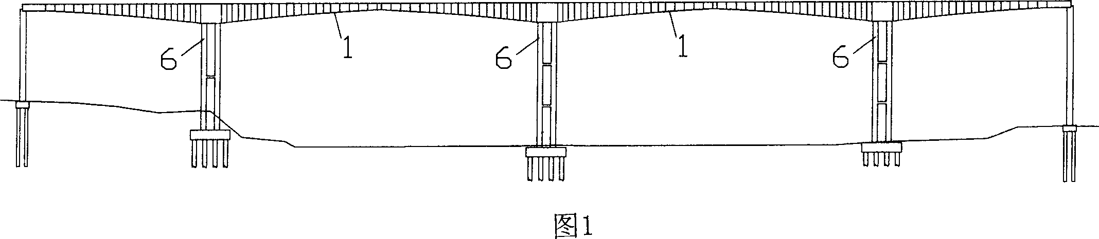
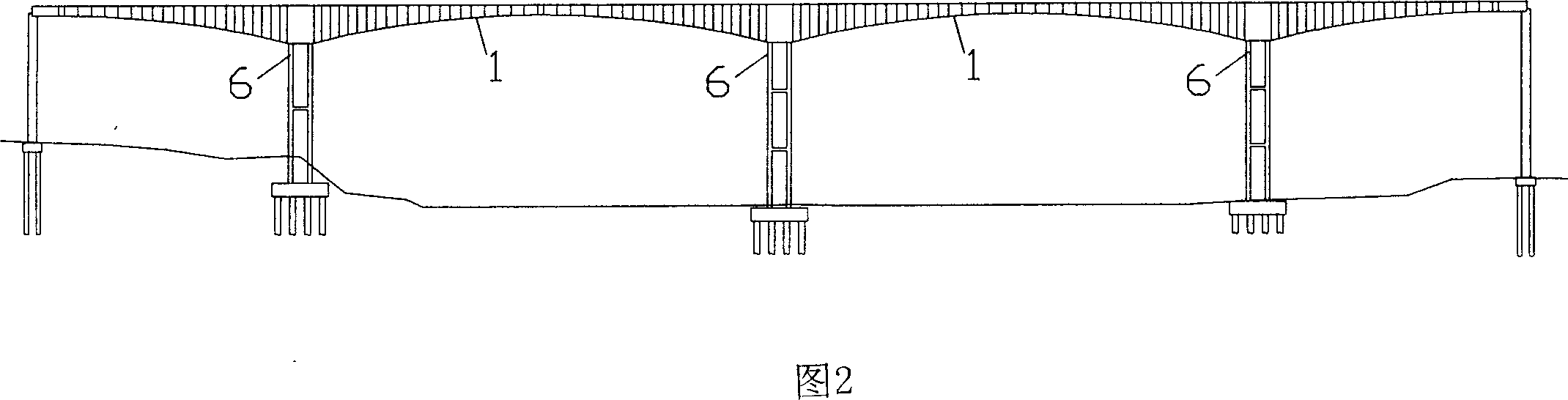
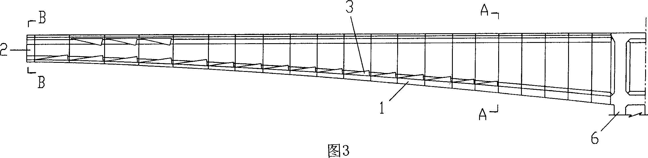
[0047] Referring to Fig. 6 to Fig. 12 and Fig. 17 to Fig. 20, the prestressed concrete variable cross-section box girder bridge with built-in slanted leg rigid frame of the present invention, including pier 6 and bottom plate 1 and web 2 constituting the box girder, is an existing The box girder of the variable cross-section box girder bridge is equipped with a rigid frame structure with oblique legs. The built-in oblique legs 42 and the bottom plate 1 of the box girder are arranged in parallel, the radial distance between the built-in inclined legs 42 and the bottom plate 1 is 1 / 4 to 1 / 5 of the total girder height H of the fulcrum, and the built-in inclined legs 42, the bottom plate 1 of the box girder and the web 2 All adopt the same section, and the thickness is 40-60cm. The lower edge of the box girder floor 1 adopts a suspension line, which has the effect of an arch bridge landscape, and the net rise-span ratio is 1 / 7 to 1 / 9. The built-in longitudinal beam 41 is set at t...


PUM


Abstract

The present invention belongs to the field of civil engineering bridge technology, and discloses a kind of built-in oblique leg rigid frame prestressed concrete non-uniform box beam bridge. It is characterized by that in its box beam interior an oblique leg rigid frame structure is set, said oblique leg rigid frame structure is formed from built-in longitudinal beam and built-in oblique leg. The built-in oblique leg and box beam baseplate are parallelly arranged and identical in thickness, and the built-in longitudinal beam and midspan baseplate are aligned and identical in thickness, the midspan baseplate, box beam baseplate and built-in longitudinal beam are combined into one body, so that said bridge structure has high integral rigidity, small deflection and strong resistance to shear, and the crossing capacity of said prestressed concrete non-uniform box beam bridge can be greatly raised.

Description

technical field [0001] The invention belongs to the technical field of civil engineering bridges, and in particular relates to a prestressed concrete variable-section box girder bridge with built-in oblique-leg rigid frame and a construction method thereof. Background technique [0002] Long-span prestressed concrete variable-section box-girder bridges are widely used bridge types at present, and continuous beams and continuous rigid-frame bridges are the most common, and they are often constructed by hanging basket cantilever casting method. Figure 1 is the facade layout of an existing long-span prestressed concrete variable-section box girder bridge, which is a continuous rigid frame bridge, the mid-span girder height is less than the fulcrum girder height at pier 6, and the bottom is the box girder floor 1 , the facade of the lower edge of the main beam is flat and arched, and is constructed by segmented hanging basket cantilever cast-in-place technology. As shown in Fig...

Claims


Application Information

Patent Timeline
Patent Type & Authority Applications(China)
IPC IPC(8): E01D2/04E01D21/10E01D101/28
Inventor 吴国松吴明生卢勤孙明星李军心舒亚健郝章喜陈为高郭宏飞范忠焕漆国秋
Owner CHONGQING JIAOTONG UNIVERSITY
Why Eureka
Try Eureka