Baseboard cable horizontal arrangement prestress concrete variable cross-section box girder bridge and construction method thereof

A concrete and prestressing technology, applied in bridges, bridge materials, bridge construction, etc., can solve problems such as uneconomical, main tensile stress cracks in web 2, large prestress loss of curved cables, etc., to simplify structural design and construction, Solve the cracks along the bridge and the effect of small prestress loss

Inactive Publication Date: 2007-06-06
CHONGQING JIAOTONG UNIVERSITY +1
View PDF0 Cites 10 Cited by
  • Summary
  • Abstract
  • Description
  • Claims
  • Application Information

AI Technical Summary

Problems solved by technology

[0005] (1) The downward radial force of the arched floor cable 5 generates shear force along the bridge direction at the position of the corresponding floor 1. Since the bottom plate 1 in the mid-span is thin, generally 25-40cm, the transverse reinforcement is arranged according to the structure, and the floor cable 5 If the downward radial force is too large, it will easily lead to shear cracks along the bridge direction in the bottom plate 1 of the middle span, and seriously cause the bridge bottom plate 1 to crack and fail.
[0006] (2) The downward radial force of the floor cable 5 also directly leads to the tension of the web 2 in the corresponding section, which may easily lead to the main tensile stress cracks in the web 2. Usually, such defects are more common in the range from L / 4 section to L / 2 section. Common, related to this, generally the beam height from L / 4 section to L / 2 section is small, and the vertical prestress is difficult to control. If the vertical effective prestress is unreliable, the disease will be aggravated
[0008] (4) The downward radial force of the floor cable 5 directly leads to the mid-span deflection
[0009] (5) The positioning of the arched floor cable 5 is difficult, the construction is not easy to control, the prestress loss of the curved cable is large, and it is uneconomical

Method used


Image

  • Baseboard cable horizontal arrangement prestress concrete variable cross-section box girder bridge and construction method thereof
  • Baseboard cable horizontal arrangement prestress concrete variable cross-section box girder bridge and construction method thereof
  • Baseboard cable horizontal arrangement prestress concrete variable cross-section box girder bridge and construction method thereof

Examples


Embodiment Construction

[0035] The present invention will be further described in detail below in conjunction with the accompanying drawings and specific embodiments.

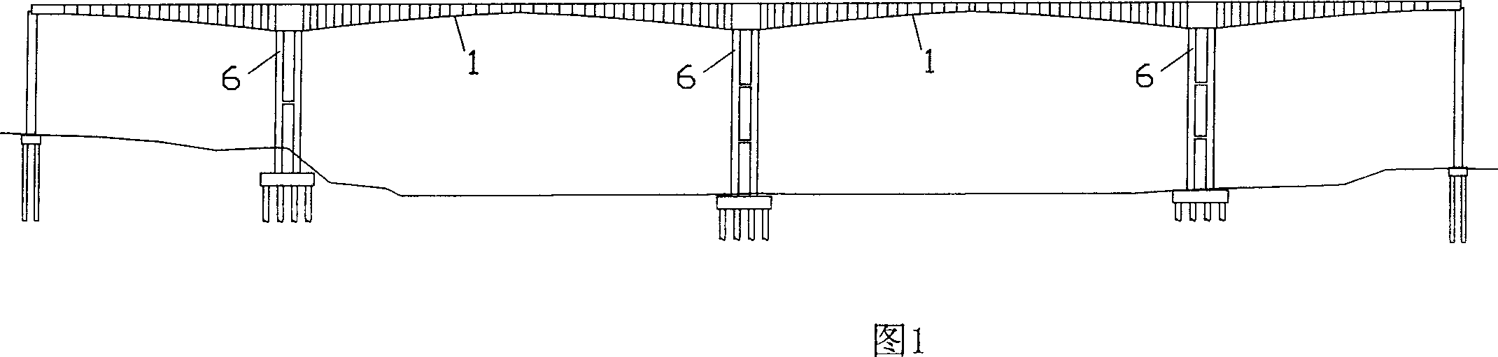
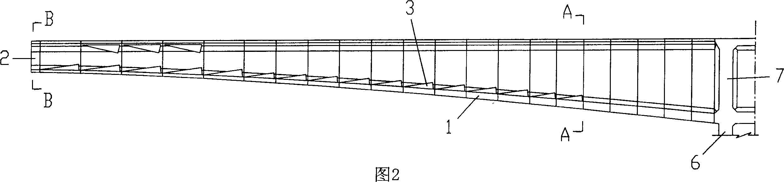
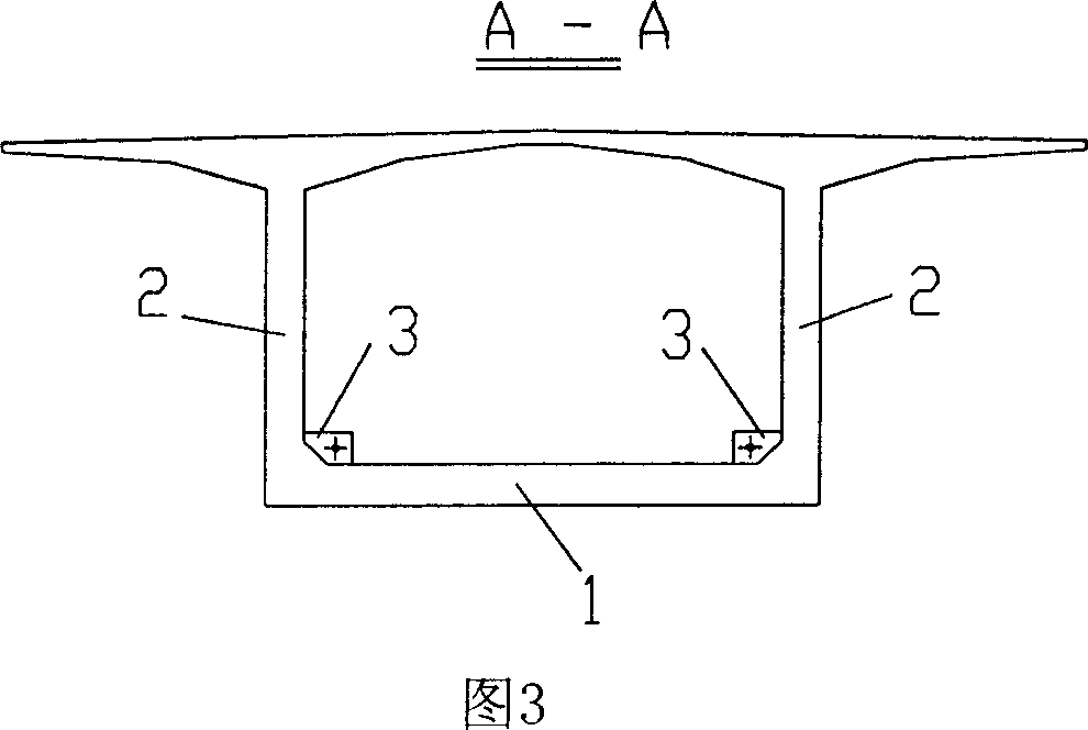
[0036] The long-span prestressed concrete variable-section box girder bridge structure with floor cables arranged horizontally according to the present invention, as shown in Fig. The mid-span mid-slab 1 of the box girder corresponds to the height of the girder, and the horizontal anchor plate 4 is arranged longitudinally, and the horizontal anchor plate 4 is integrated with the box girder bottom plate 1 in the section near the L / 2 section to the 3L / 8 section of the mid-span, and the rest of the positions are integrated with the box girder bottom plate 1. The base plate 1 is separated, and the thickness of the horizontal anchor plate 4 is consistent with that of the mid-span base plate 1, generally 25-40 cm. As shown in Figures 11 to 13, the bottom cable 5 is arranged in the horizontal anchor plate 4, and the sawtooth block 3 is set o...


PUM


Abstract

The present invention belongs to the field of civil engineering bridge technology, and relates to a baseplate ropes horizontally-arranged prestressed concrete non-uniform box beam bridge. It is characterized by that in the position of midspan baseplate which is correspondent to the beam height in the box beam interior a horizontal anchor plate is set longitudinally, said horizontal anchor plate and box beam baseplate are combined into one body, the thickness of said horizontal anchor plate is identical to that of midspan baseplate, the baseplate ropes are arranged in the horizontal anchor plate interior, and said horizontal anchor plate and box beam can be cast in-situ together. Said invention can raise durability of the bridge and can greatly raise crossing capacity of said bridge.

Description

technical field [0001] The invention belongs to the technical field of civil engineering bridges, and in particular relates to a prestressed concrete variable-section box girder bridge with floor cables arranged horizontally and a construction method thereof. Background technique [0002] Long-span prestressed concrete variable-section box-girder bridges are widely used bridge types at present, and continuous beams and continuous rigid-frame bridges are the most common, and they are often constructed by hanging basket cantilever casting method. As shown in Figure 1, it is a schematic structural diagram of a continuous rigid frame bridge. The main girder between the piers 6 and its bottom plate 1 are arched, and the height of the girder at mid-span is smaller than the height of the fulcrum at the 6 piers. [0003] As shown in Fig. 2 to Fig. 4, the commonly used cross-section form of this kind of variable cross-section box girder bridge is a single-box single-chamber cross-sec...

Claims


Application Information

Patent Timeline
Patent Type & Authority Applications(China)
IPC IPC(8): E01D2/04E01D21/10E01D101/28
Inventor 吴国松吴明生卢勤孙明星李军心舒亚健郝章喜陈为高郭宏飞范忠焕漆国秋
Owner CHONGQING JIAOTONG UNIVERSITY
Why Eureka
Try Eureka