
Welding steel floor

A steel floor, welding technology, applied in the direction of floor, building, building structure, etc., can solve the problems of heavy steel floor, large equipment investment, high production cost, and achieve light weight, low production cost and convenient production. Effect

Inactive Publication Date: 2007-06-06
黄磊
View PDF0 Cites 2 Cited by
  • Summary
  • Abstract
  • Description
  • Claims
  • Application Information

AI Technical Summary

Problems solved by technology

[0003] The technical problem to be solved by the present invention is to provide a welded steel floor to solve the problems of heavy weight, complex process, large equipment investment and high production cost of the existing steel floor

Method used


Image

  • Welding steel floor
  • Welding steel floor

Examples


Embodiment Construction

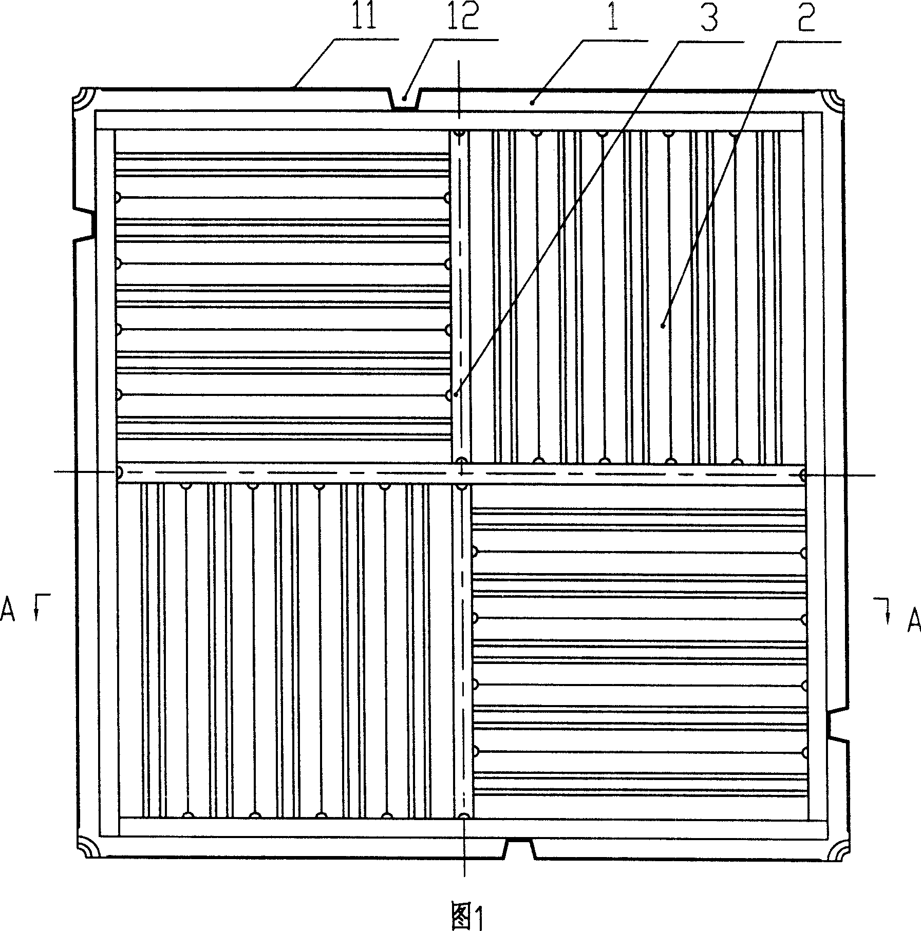
[0014] The welded steel floor of the present invention as shown in Figure 1 and Figure 2 includes a panel 1, the four sides of the panel 1 have flanges 11 extending downward along the panel surface, the flanges 11 are perpendicular to the panel surface, and the four corners of the panel 1 are bent downward Folded into a 1 / 4 dish shape, the top of the corner is concave arc, the four sides of the panel 1 are provided with openings 12, the back of the panel 1 is welded with a reinforcement plate 2 and a "Tian"-shaped reinforcement frame 3, and the reinforcement plate 2 is a wave-shaped folding plate , the crease directions of the two reinforcing plates 2 on the same side are perpendicular to each other, and the reinforcing plates 2 are arranged in the strengthening frame 3 in the shape of a "field".


PUM


Abstract

The present invention relates to a steel floor board, in particular, it relates to a welded steel floor board. It includes face board, reinforcing board welded on the back surface of said face board and reinforcing frame, the reinforcing board is set in the reinforcing frame. Said invention is light in weight, simple in structure and convenient for production.

Description

technical field [0001] The invention relates to a steel floor, in particular to a welded steel floor. Background technique [0002] The general structure of the existing steel floor is as follows: it includes a panel and a bottom plate, the cavity formed by the panel and the bottom plate is filled with filling materials, the bottom plate is recessed with a plurality of bowl-shaped reinforcements, and the bottom plate is provided with filling holes. This structural floor is extremely heavy, so people have developed a welded or riveted hollow floor. The structure of the panel and the bottom plate is similar to the aforementioned steel floor. There is no filling material in the space, and the weight of this hollow floor is greatly reduced compared with ordinary steel floors. However, because the bottom plate needs to be punched out of a bowl shape for reinforcement, the amount of material is still relatively large, and the weight is still relatively large, and the connection be...

Claims


Application Information

Patent Timeline
Patent Type & Authority Applications(China)
IPC IPC(8): E04F15/06
Inventor 黄磊
Owner 黄磊
Learn More