Hinge structure

A hinge structure, pivot technology, applied in the field of free positioning hinge structure, can solve problems such as labor

Inactive Publication Date: 2007-06-13
HONG FU JIN PRECISION IND (SHENZHEN) CO LTD +1
View PDF0 Cites 11 Cited by
  • Summary
  • Abstract
  • Description
  • Claims
  • Application Information

AI Technical Summary

Problems solved by technology

Although this hinge structure can realize the rotation of the liquid crystal screen, however, this kind of hinge structure is relatively laborious when adjusting the angle of the liquid crystal screen.

Method used


Image

  • Hinge structure
  • Hinge structure
  • Hinge structure

Examples


Embodiment Construction

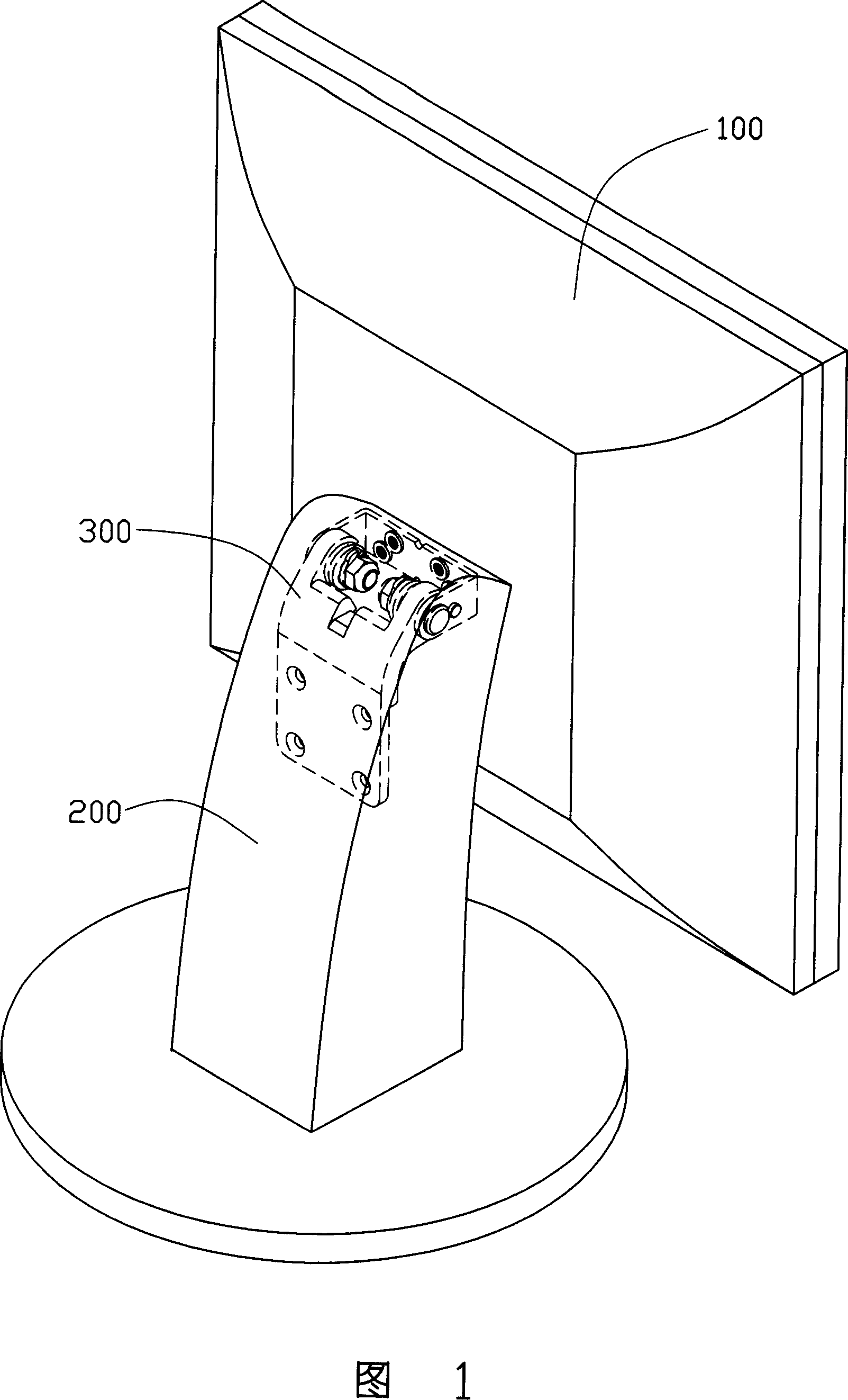
[0012] The hinge structure of the present invention is illustrated by taking the application to a liquid crystal display as an example.

[0013] Referring to FIG. 1 , the liquid crystal display includes a display case 100 and a stand 200 , the display case 100 and the stand 200 are rotatably connected by a hinge structure 300 .

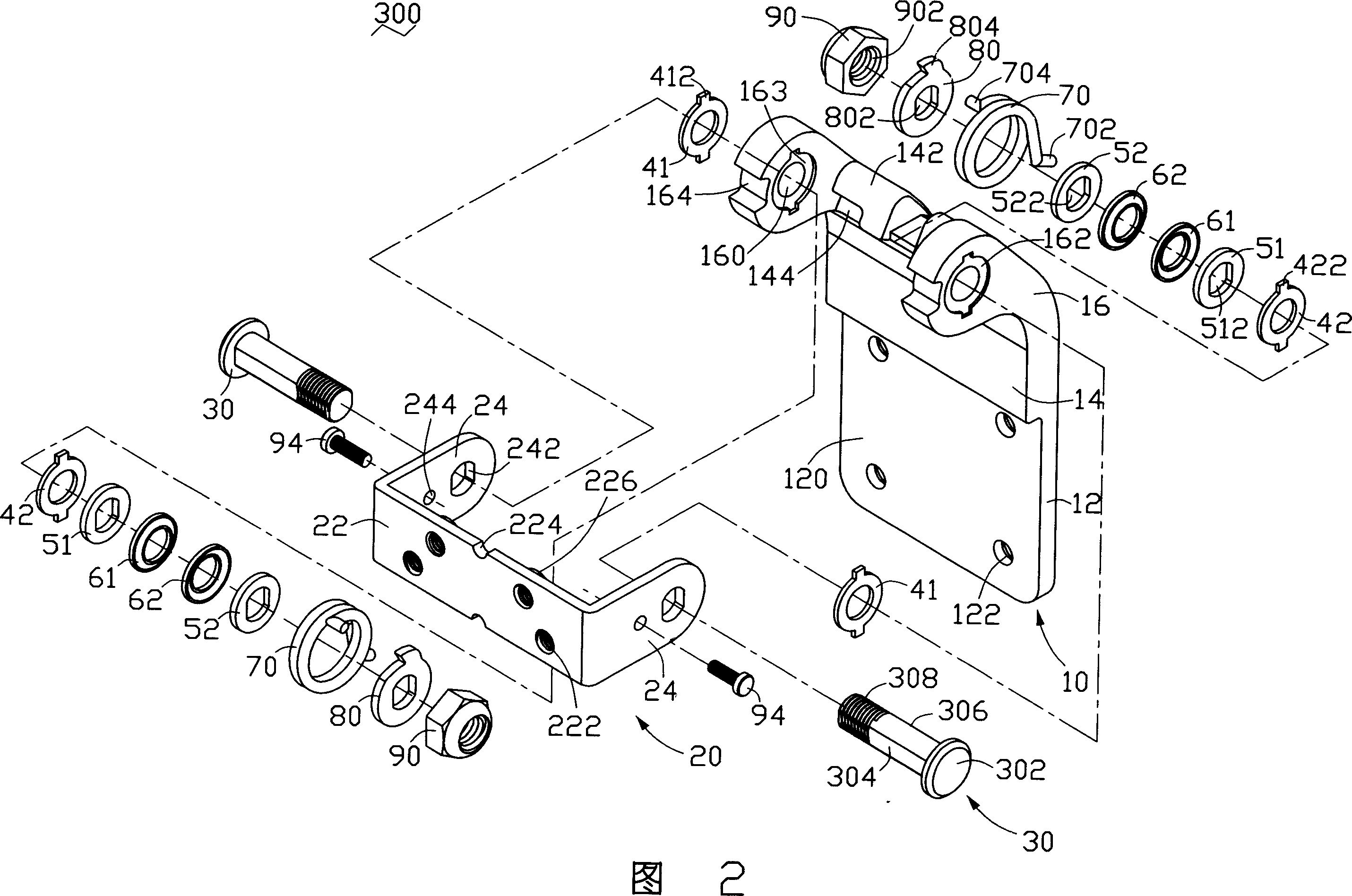
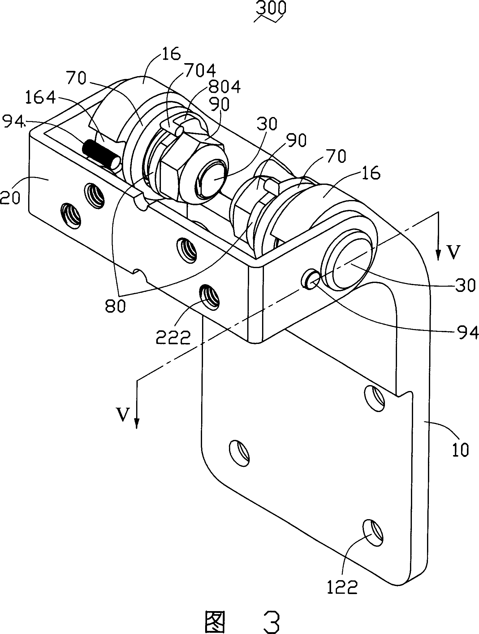
[0014] Please refer to FIG. 2 to FIG. 4 , the hinge structure 300 includes a bracket 10 , a base 20 and two pivoting devices (not shown). Each pivoting device all comprises a pivot 30, a friction plate 41, a friction plate 42, a washer 51, a washer 52, a shrapnel 61, a shrapnel 62, a torsion spring 70, a spacer 80, A nut 90 and a screw 94 .

[0015] The bracket 10 includes a mounting portion 12 , a connecting portion 14 and two extending portions 16 . The mounting portion 12 is plate-shaped and includes a surface 120 , and four mounting holes 122 are evenly opened on the mounting portion 12 , and the mounting holes 122 are through holes. The connec...


PUM


Abstract

The invention discloses hinge structure used in LCD etc electronic equipment. It includes one support, one base, and one pin joint device. The pin joint device includes one pivot, one elastic piece, one blocking piece, and one fixing piece. The support is set one pivot hole and one gap. The base is set one deforming hole. The pivot includes one fixed part and one pivot rotating part. The elastic piece includes the first and second fixed ends which are respectively fixed on the support and the base. The blocking piece is set at the gap of the base. The pivot penetrates the pivot hole, deforming hole, and fixing piece which restricts the support, base, and elastic piece together with the pivot fixed part. The hinge structure of the invention can freely locate, and smoothly rotate.

Description

【Technical field】 [0001] The present invention relates to a hinge structure, in particular to a freely positioning hinge structure. 【Background technique】 [0002] With the wide application of calculators, the monitors used with them also tend to be thinner and lighter. The traditional display is a cathode ray tube (CRT, Cathode Ray Tube) display, which is not only bulky but also quite heavy, so liquid crystal displays appear on the market. Liquid crystal displays have the advantages of small size, light weight, high definition and low radiation, and are widely accepted by the market. In addition, in order to make the liquid crystal display have a better viewing angle, it is usually necessary to rotate or swing the screen at a certain angle through a hinge structure. [0003] An existing hinge structure, which includes: a fixed seat, a pivot, gaskets for a plurality of oil storage holes and a fixed assembly; the fixed seat is bent into an L-shaped plate structure, and a fl...

Claims


Application Information

Patent Timeline
Patent Type & Authority Applications(China)
IPC IPC(8): F16C11/04
CPCY10T16/540345E05D11/06F16M11/10E05Y2900/606E05D11/087F16M2200/041
Inventor 胡安奎
Owner HONG FU JIN PRECISION IND (SHENZHEN) CO LTD
Why Eureka
Try Eureka