Device for moulding chopped preparations

A molding device and mincing technology, applied in the direction of meat extrusion, slaughtering, household appliances, etc., can solve the problems of complex and expensive implementation of automatic stop equipment

Active Publication Date: 2007-06-20
SEB SA
View PDF2 Cites 1 Cited by
  • Summary
  • Abstract
  • Description
  • Claims
  • Application Information

AI Technical Summary

Problems solved by technology

However, the automatic stop devices described in these various documents are complex and expensive to implement, main

Method used


Image

  • Device for moulding chopped preparations
  • Device for moulding chopped preparations
  • Device for moulding chopped preparations

Examples


no. 3 example Embodiment

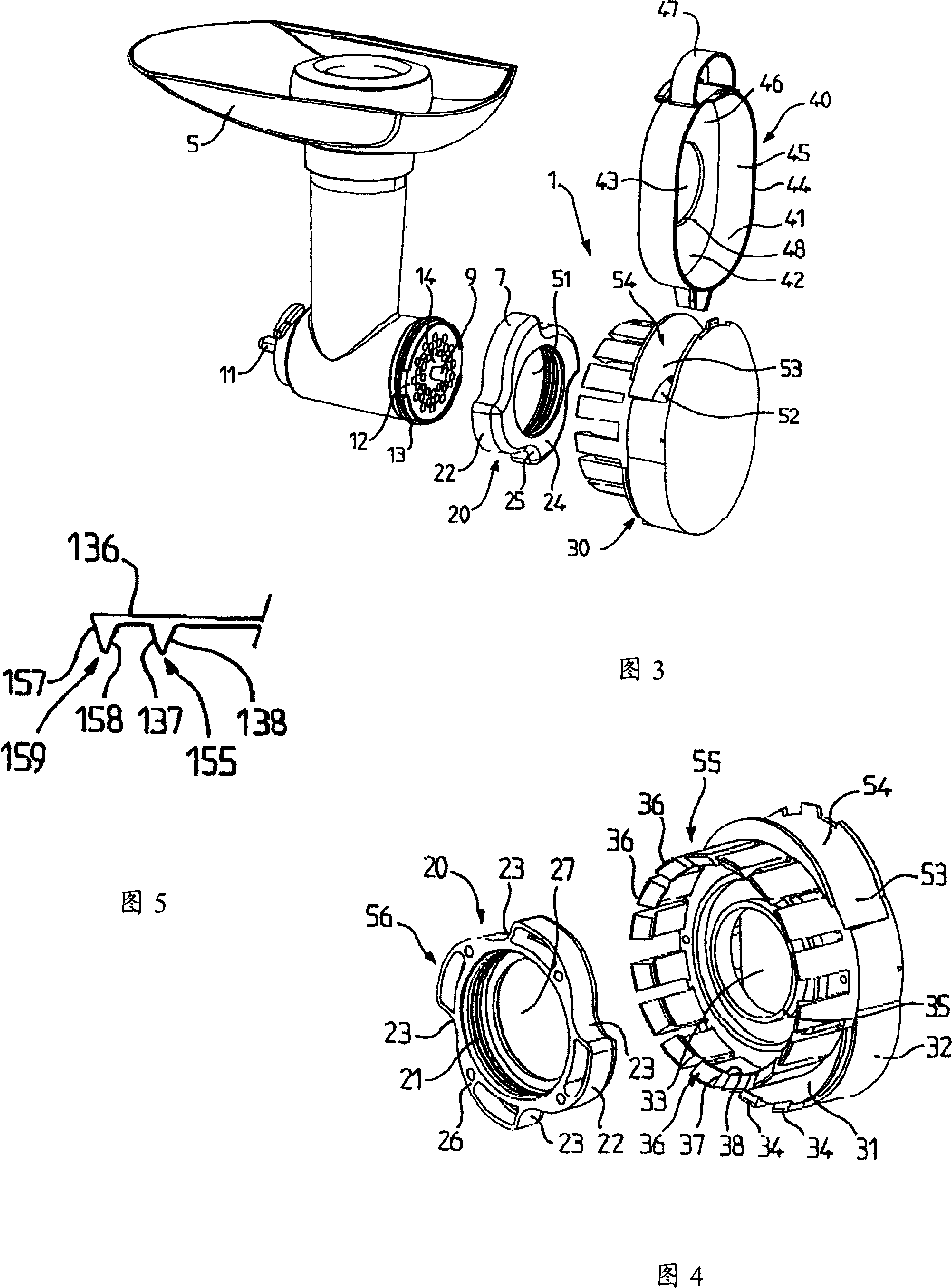
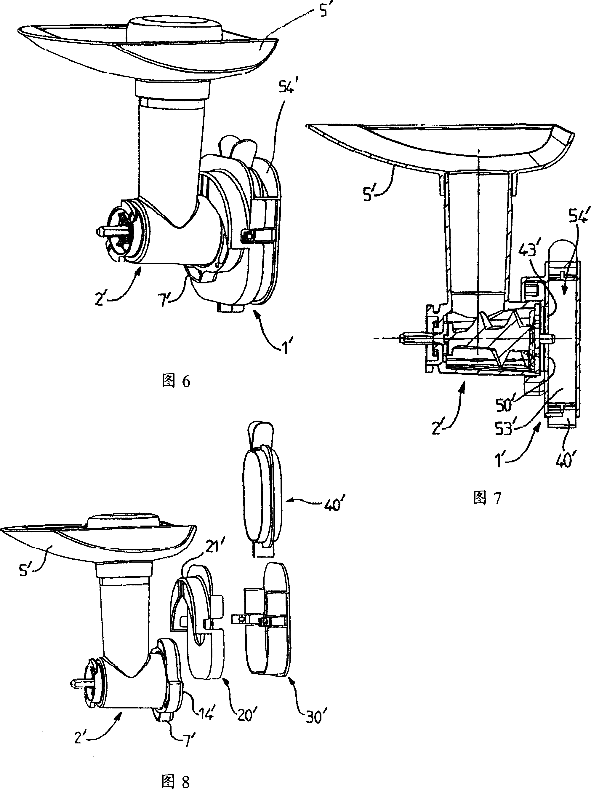
[0098] The user installs the cutter 2" with the nut on the mincer motor and then installs the mounting part 21" of the support 20" on the nut 7". The user then assembles the shell assembly 30" with the support 20" by placing the support wall 33" on the rod 70". The user places the ground article forming attachment 40"on the front wall panel 31"of the housing assembly 30"by using, for example, the gripping device 47". To this end, the user can apply pressure to the peripheral wall 41 ″ to deform the central elastic hinge 60 ″ so that the outer transverse ribs 63 ″, 64 ″ can abut against it inside the side wall 32 ″. The chamber 53 ″ is supported by the support 20 "And shell assembly 30 " form, and it has an introduction port that places crushed product forming attachment 40 ". Compared with the situation in the original state, the end edge 48 of the peripheral wall panel 41 " placed in the chamber 53 " ″, 49″ close to each other. If desired, the peripheral wall 41″ can also be...


PUM


Abstract

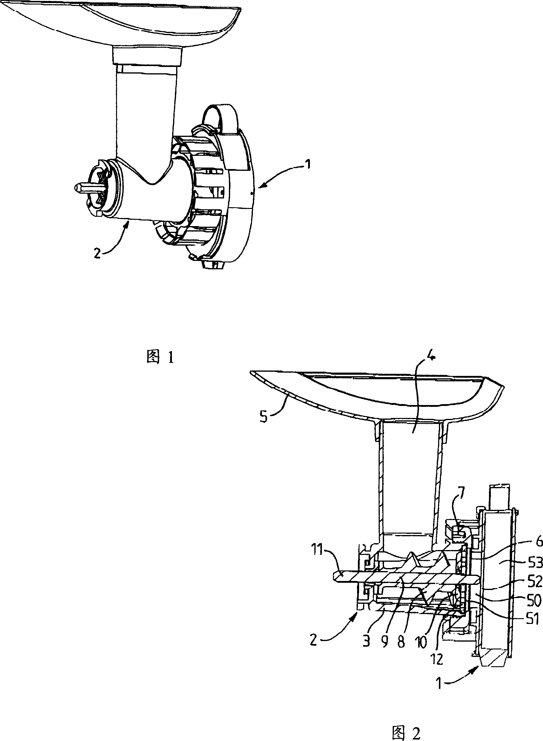
The device has a support (20'') and a case element defining a duct (50'') emerging in a housing (53''). The support has a locking unit (55'') engaged with a retaining unit (56''). A chopped preparation e.g. fish, molding accessory (40'') defines a chopped food reception space in which pressure is exerted by chopped food for releasing the unit (55'') engaged with the unit (56'') to allow the displacement of the element with respect to the support providing an expansion space for the food. The element remains connected to the support, after the unit (55'') is disengaged from the unit (56''), and allow case groupware (30'') shift relative to support (20''), so that twist food release more space.

Description

technical field [0001] The invention relates to the technical field of cooking household appliances, in particular to a molding device for minced products. Background technique [0002] Home mincers sometimes come with molds for hand filling, such as those used to reconstitute minced meat into patties. But the filling of the mold is very cumbersome. In addition, the user must continuously operate the mincer to mince the pieces of meat, and then use a cover to compress the collected mince in the mould. [0003] Document FR1299087 describes a device placed at the end of a screw-type mincer for reconstituting ground meat into patties. The ground product is collected in a receptacle that is slidably mounted within the frame of the apparatus. When the receptacle is filled, a push rod mounted in the receptacle activates a frame mounted switch which stops the machine engine. Documents FR2564290, FR2571596, FR2589686, and EP0321766 disclose additional automatic stop devices for ...

Claims


Application Information

Patent Timeline
IPC IPC(8): A22C7/00A47J44/02
CPCA22C7/003
Inventor 让·保罗·埃斯泰格诺帕特里克·夏尔
Owner SEB SA
Why Eureka
Try Eureka