Electric junction box

A technology for electrical junction boxes and electrical conductors, which is applied in the direction of conductive connections, electrical components, circuits, etc., and can solve the problem of large size of electrical junction boxes

Inactive Publication Date: 2007-06-20
SUMITOMO WIRING SYST LTD
View PDF1 Cites 3 Cited by
  • Summary
  • Abstract
  • Description
  • Claims
  • Application Information

AI Technical Summary

Problems solved by technology

Therefore, the electrical junction bo

Method used


Image

  • Electric junction box
  • Electric junction box
  • Electric junction box

Examples


Embodiment Construction

[0054] Embodiments of the present invention will be described with reference to the drawings.

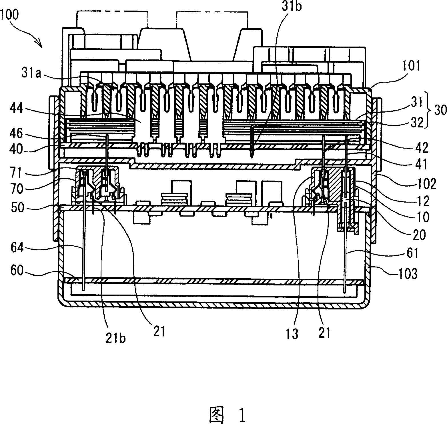
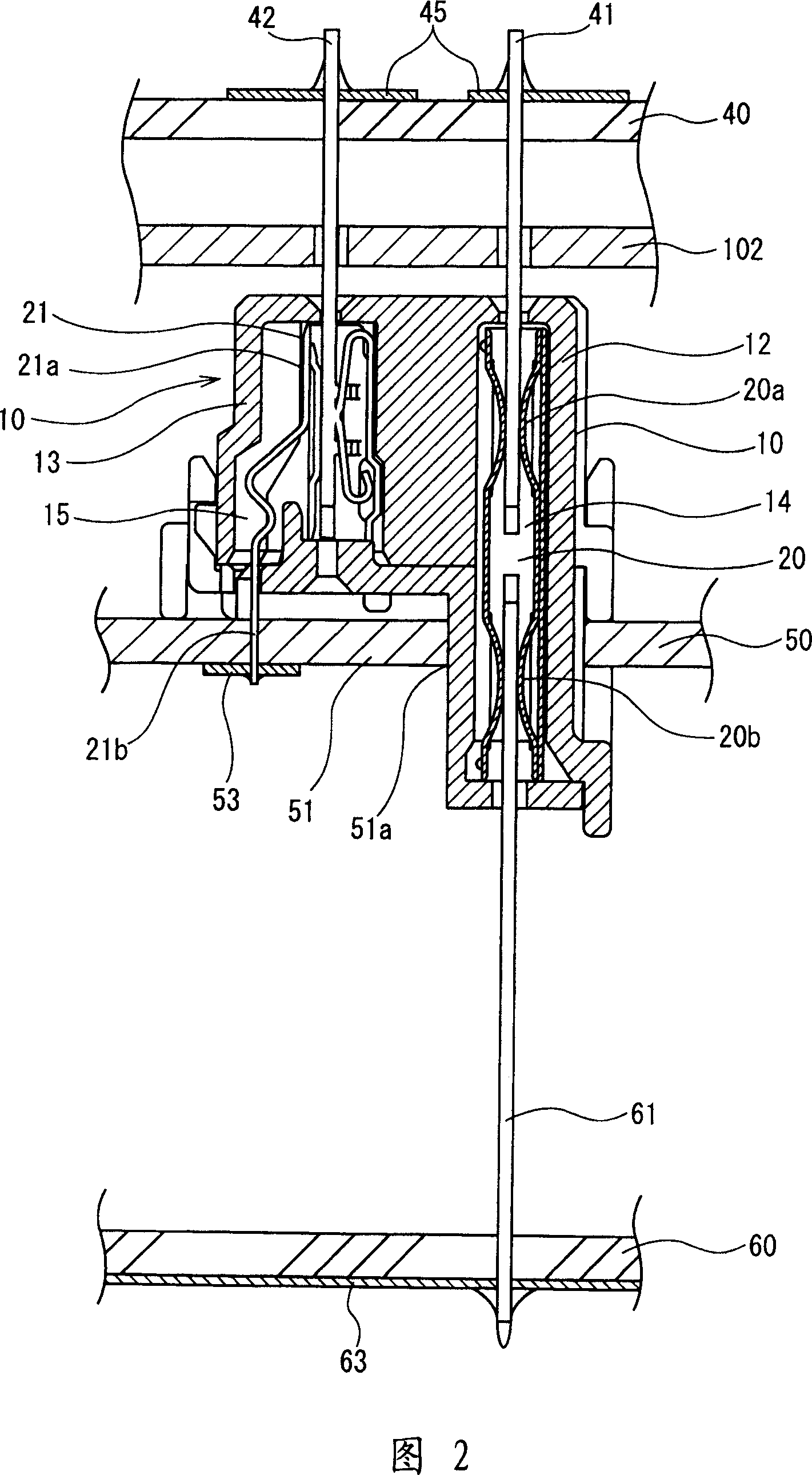
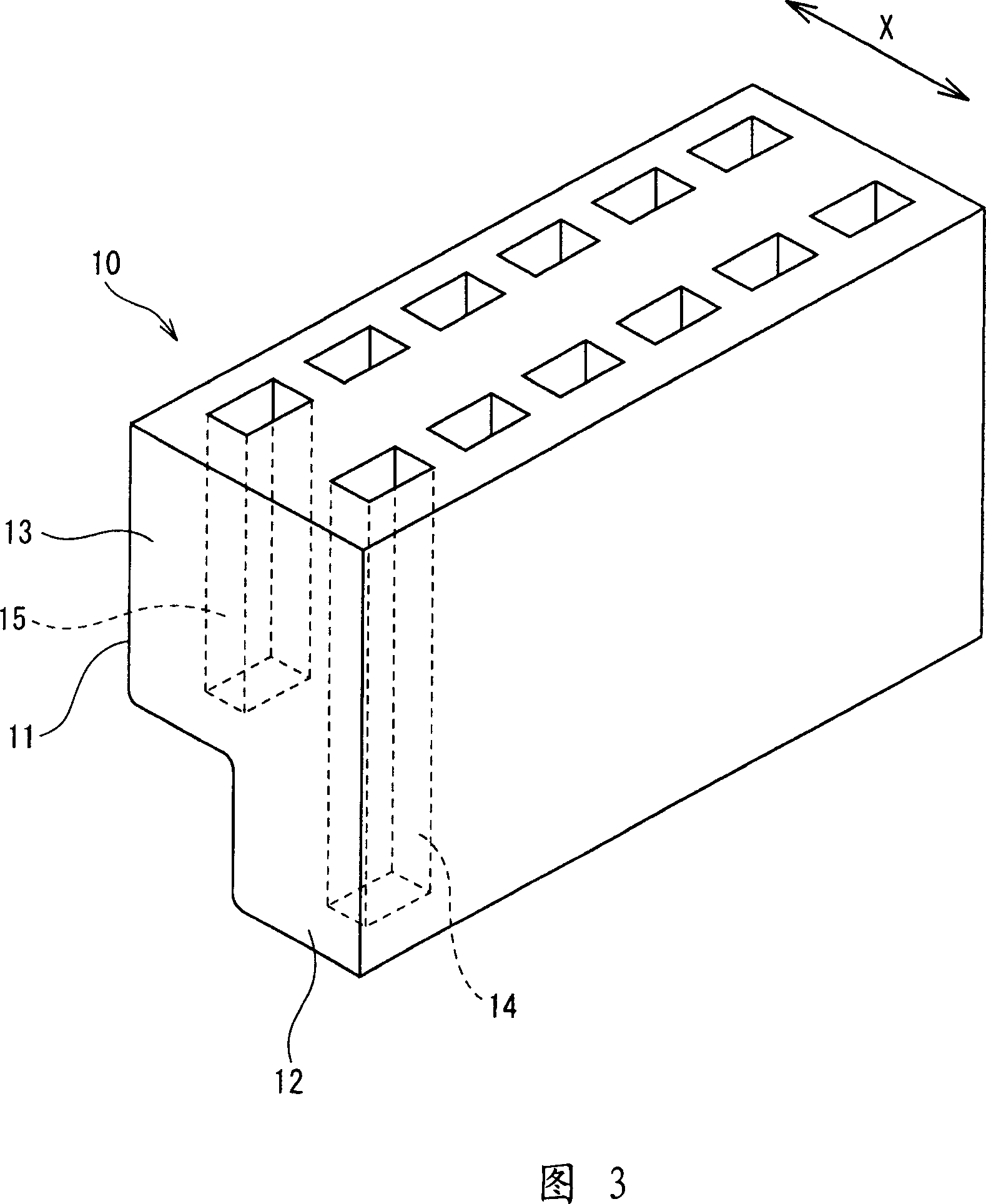
[0055] 1 to 3 show a first embodiment of the invention. The case of the electrical junction box 100 constituted by the upper case 101, the middle case 102 and the lower case 103 combined with each other accommodates the stack 30 and the three printed circuit boards 40, 50 and 60, the stack consisting of busbars (bus bars) 31 and insulating boards 32 are stacked alternately, and three printed circuit boards 40, 50 and 60 are vertically separated at a predetermined interval, and each electrical conductor of the three printed circuit boards 40, 50 and 60 They are connected to each other through the relay connector 10 .

[0056] In detail, the stack 30 and the first printed circuit board 40 are accommodated in a space surrounded by the upper case 101 and the middle case 102 , and the stack 30 is vertically stacked on the first printed circuit board 40 . The second printed circuit boar...


PUM


Abstract

Three printed boards are stored in a case, and a relay connector (10) for connecting the three printed boards is mounted on the second printed board (50) at the middle position. The relay connector (10) is provided with a first terminal storing part (14), which is long in a vertical direction, and a short second terminal storing part (15). The relay connector connects a terminal pin (41) of the first printed board (40) at an upper position with a terminal pin (61) of the third printed board (60) at a lower position, via a long first relay terminal (20) stored in the first terminal storing part (14), while connecting a terminal pin (42) of the first printed board and/or the terminal pin of the third printed board with a conductor (53) of the second printed board, via a short second relay terminal (21) stored in the second terminal storing part (15).

Description

technical field [0001] The present invention relates to an electrical junction box in which electrical conductors of at least three circuit elements housed in a housing are connected to each other via a relay connector. Background technique [0002] Conventionally, the case of an electrical junction box mounted on a vehicle body accommodates: a laminate consisting of bus bars formed by punching conductive metal plates into a predetermined shape, and insulating plates Insulating plates are alternately laminated on the respective bus bars; and a circuit element constituted by an insulating substrate on which electrical conductors such as copper foil are printed in a desired pattern to form a circuit board. When one housing accommodates a plurality of circuit elements stacked on each other, electrical conductors of the respective circuit elements are connected to each other via relay connectors. [0003] An electrical junction box 1 of this type accommodating relay connectors ...

Claims


Application Information

Patent Timeline
IPC IPC(8): H02G3/16H01R12/50
CPCH05K2201/10659H01R9/2466H05K3/3447H05K2201/10303H05K2201/10189H01R9/2425H05K1/144H05K7/026
Inventor 早川达也冈达也
Owner SUMITOMO WIRING SYST LTD
Why Eureka
Try Eureka