Centrifugal pressurizing propeller structure

A centrifugal, impeller technology, applied in non-variable-capacity pumps, components of pumping devices for elastic fluids, machines/engines, etc., can solve problems such as high cost, increased flow channel resistance, and reduced operating efficiency Achieve the effect of solving structural problems, reducing operating noise, and improving balance

Active Publication Date: 2010-04-07
IND TECH RES INST
View PDF12 Cites 0 Cited by
  • Summary
  • Abstract
  • Description
  • Claims
  • Application Information

AI Technical Summary

Problems solved by technology

For example, by changing the flow force design of the flow force components, better flow field design and unit efficiency can be obtained, and the generation of broadband noise can be reduced; this method has many difficulties in actual design, because it requires a wide range of operation and regulation. For mechanical devices, it is not easy to obtain a combination of parameters for wide-area and high-efficiency operation, which forms a design bottleneck
[0007] There are also other methods to reduce discrete monotonic noise, such as Figure 4 The U.S. Patent No. 3,635,579 shown in the case is to add a soundproof casing 20 outside the turbine casing to reduce the noise of the impeller of the centrifugal rotary pressurization mechanism. This method has complex structure and high cost. disadvantages, it is difficult to promote on a large scale
[0008] like Figure 5 Shown U.S. Patent No. 4,411,592 case, it is to additionally arrange a porous sound-absorbing material 25 (Absorber Materiel) on the straight wall flow channel of impeller outlet and diffuser, reach the effect of reducing noise, or as U.S. Patent No. Case No. 4,504,188 and Case No. 5,249,919 also have similar designs; although this type of design can reduce fluid noise, it increases flow channel impedance and reduces operating efficiency, and it is difficult to solve practical problems

Method used


Image

  • Centrifugal pressurizing propeller structure
  • Centrifugal pressurizing propeller structure
  • Centrifugal pressurizing propeller structure

Examples


Embodiment 1

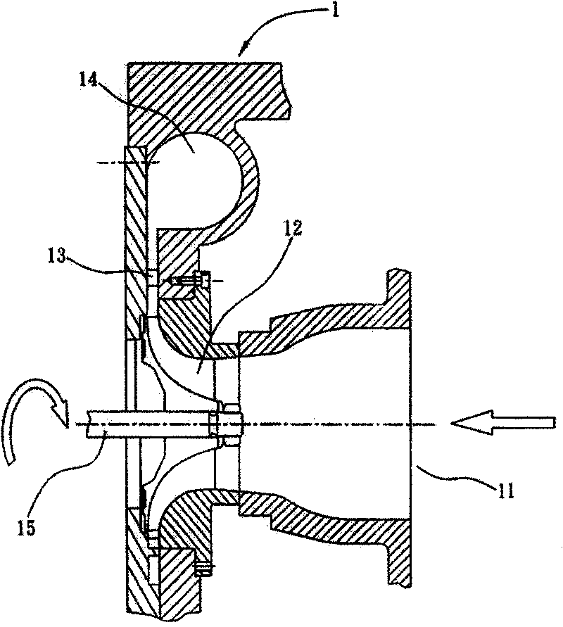
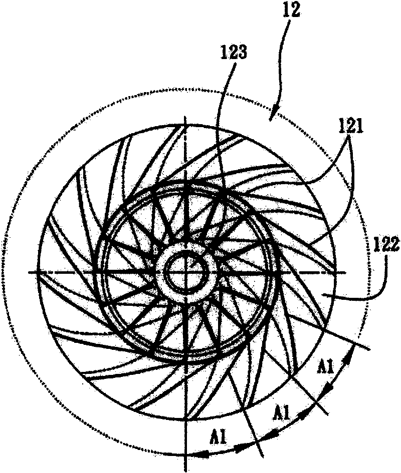
[0031] The centrifugal pressurized impeller structure 30 proposed by the present invention is applied to the above-mentioned existing centrifugal rotary pressurization device, and the impeller structure is as follows Figure 6A and Figure 6B As shown, the impeller structure includes an arc-shaped impeller body 31, which has a shaft hole 32 in the center of the body 31, and a wheel shaft 33 can pass through it and be perpendicular to the plane of the body 31; meanwhile, the present invention uses the circular The arc-conical body 31 is equally divided into multiple equal parts, and the embodiment 1 as shown in the figure is divided into two equal parts, and two groups of blade groups 35 are set, all have a plurality of blades 36 in the two groups of blade groups 35, to wrap around the The wheel shaft 33 is sequentially arranged around the wheel shaft 33; wherein, the adjacent blades 36 in each blade group 35 are arranged along the radial direction of the conical arc surface of...

Embodiment 2

[0036] Design of the present invention is except above-mentioned embodiment 1, also can change the number of vane group, just this body is equally divided into other quantities, as Figure 8 The shown embodiment 2 is that the main body 31 is divided into three equal parts, and three groups of blade groups 35 are designed, so that the interval angles between adjacent blades 36 differ by a fixed increasing angle α, and each blade group 35 The number of blades 36 and the corresponding interval angles are the same, that is, the blades 36 in the three groups of blades 35 are 120 degrees symmetrical to each other.

Embodiment 3

[0038] Figure 9 It is embodiment 3 of the present invention, it divides this body 31 into four equal parts, and designs four groups of vane groups 35, makes the spacing angle between adjacent vanes 36 differ by a fixed amplifying angle α respectively, and each vane The number of blades 36 in the group 35 and the corresponding interval angles are the same, that is, the blades 36 in the four groups of blade groups 35 are mutually symmetrical at 90 degrees.

[0039] Therefore, the number of blade sets 35 of the present invention is not limited, and the body 31 can also be divided into other numbers and the corresponding number of blade sets 35 is designed, only need to form a regular periodic change, unequal pitch blades 36 The impeller structure is sufficient; in addition, the interval angles of adjacent blades 36 in the same group of blade groups 35 do not necessarily need to differ by a fixed increase angle α, and can also be at any different interval angles respectively, and...


PUM


Abstract

A centrifugal pressurizing blade wheel structure with low noise is composed of a main body with conic-arc shape and a central axle hole, and multiple groups of multiple blades with regularly periodicvariation of unequal gaps between adjacent blades. All the blades in a group have different angles.

Description

technical field [0001] The present invention relates to a centrifugal pressurized impeller structure, in particular to a low-noise centrifugal pressurized impeller structure used in a centrifugal rotary pressurized mechanical device. Background technique [0002] For existing centrifugal rotary pressurized mechanical devices such as centrifugal compressors or centrifugal fans, it uses the high-speed rotation of the centrifugal impeller structure of the mechanical device to absorb the fluid (such as refrigerant, air, water, etc.) ) work to achieve the function of pressurizing and transporting fluid, and then obtain the required pressure and discharge flow, and exert the designed effect. [0003] figure 1 It is the usual structure of the existing centrifugal rotary pressurized mechanical device. The pressurized mechanical device 1 includes a fluid suction port 11, a centrifugal impeller 12, a diffuser assembly 13 (Diffuser), a volute 14 (Volute Casing) and an impeller shaft ...

Claims


Application Information

Patent Timeline
Patent Type & Authority Patents(China)
IPC IPC(8): F04D29/30F04D29/66
Inventor 强忠萍陈景富周永乐严正忠
Owner IND TECH RES INST
Why Eureka
Try Eureka