Flow-driven oscillating acoustic attenuator

a technology of oscillating acoustic attenuator and fluid flow, which is applied in the direction of mechanical apparatus, air flow influencer, transportation and packaging, etc., can solve the problems of large amount of acoustic energy, high noise level, not only the effect of creating, and reducing sound pressure levels

Active Publication Date: 2010-09-21
CONTINUUM DYNAMICS
View PDF9 Cites 6 Cited by
  • Summary
  • Abstract
  • Description
  • Claims
  • Application Information

AI Technical Summary

Benefits of technology

[0012]It is an object of the present invention to use flow-driven oscillating acoustic attenuators to reduce sound pressure levels generated by the flow over a cavity.

Problems solved by technology

The issue arises when fluid flowing over a more or less continuous surface encounters a cavity in the surface, which creates a large amount of acoustic energy.
This type of cavity flow not only creates high noise levels but also generates severe vibrational stresses.
Failing to mitigate cavity resonance increases operational noise levels and can lead to fatigue-induced structural damage.
In aircraft weapons bays, the pressure waves associated with the acoustic energy can also interfere with accurate delivery of weapons such as missiles and so-called “smart bombs.”
Drawbacks of known passive devices include a limited operating range, meaning that they are only effective through a relatively narrow range of flow conditions.
As for active systems, they require an actuation system, which can be bulky and difficult to implement in flow environments encountered in aircraft applications.
They can also require a significant amount of energy to operate and entail a weight penalty, both of which can be important considerations in aircraft applications especially.
Since these are active devices, they require actuators that can move the flaps through the required range of motion (amplitude), and such actuators carry significant, usually unacceptable, weight and power penalties.
The same problem is encountered with pulsed jet devices, namely that generating sufficient mass fluxes to affect the flow in the cavity generally requires an unacceptable level of external power.

Method used


Image

  • Flow-driven oscillating acoustic attenuator
  • Flow-driven oscillating acoustic attenuator
  • Flow-driven oscillating acoustic attenuator

Examples


Embodiment Construction

[0038]General Principles Underlying the Invention

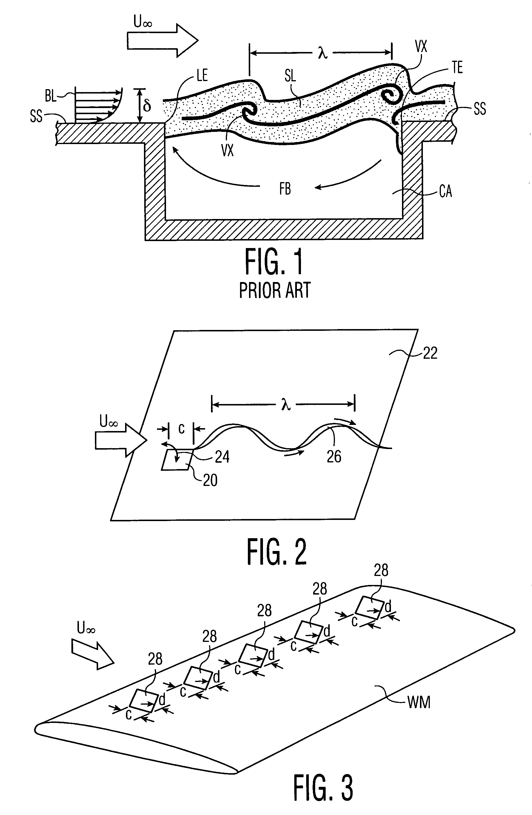
[0039]It has long been known that under certain conditions aerodynamic systems such as wings and control surfaces will undergo limit cycle oscillation (LCO). Under such conditions, the energy required to maintain the LCO motion is being extracted from the surrounding flow field. For dynamic systems this is a special form of “flutter” where the energy extracted from the flow field is exactly equal to energy lost to structural, aerodynamic, and other forms of damping. There has been a great deal of research over the years to develop methods for accurate prediction of the onset of LCO and flutter, in furtherance of the usual design approach of predicting the onset of flutter using available computational techniques, and then, if necessary, redesigning the system to avoid creating conditions where it will exist.

[0040]In contrast, the present invention seeks not to avoid such oscillations, but to use them to power vortex generators and cau...


PUM


Abstract

An apparatus for attenuating acoustic resonance generated by flow over a cavity in a surface comprises a plurality of flat flaps proximate to an upstream edge of the cavity. The flaps are disposed in an array spaced in a width direction of the cavity edge, and are oscillated by the flow in two degrees of freedom solely by the flow, independent of an actuation mechanism. Each flap includes a first hinge generally coextensive with the surface for enabling oscillation in a first degree of freedom and a second hinge orthogonal to the first hinge and forming a tab for enabling oscillation in a second degree of freedom. The hinges are constructed with torsional spring constants that provide predetermined oscillation frequencies and magnitudes. The apparatus can include a deployment mechanism for moving each flap between a stowed position wherein it is generally flush with the surface and a deployed position wherein the flap can be oscillated by the flow.

Description

CROSS-REFERENCE TO RELATED APPLICATIONS[0001]This application claims the benefit of U.S. provisional application No. 60 / 879,545, filed Jan. 10, 2007, the contents of which are incorporated herein by reference.BACKGROUND OF THE INVENTION[0002]1. Field of the Invention[0003]The present invention relates to an apparatus and method for attenuating acoustic energy in a fluid flow, and more particularly, to apparatus and methods for mitigating the acoustic energy in the flow over a cavity.[0004]2. Description of Related Art[0005]The problems caused by acoustic resonance associated with flow over a cavity have been studied for at least 50 years. The issue arises when fluid flowing over a more or less continuous surface encounters a cavity in the surface, which creates a large amount of acoustic energy. This situation occurs in contexts ranging from landing gear wells and weapons bays in airplanes, to gas transport and piping systems, to sunroofs in automobiles. This type of cavity flow not...

Claims


Application Information

Patent Timeline
Patent Type & Authority Patents(United States)
IPC IPC(8): B64C23/06
CPCB64C23/005F15D1/10Y02T50/166B64C2230/24B64C2230/08Y02T50/10
Inventor BILANIN, ALAN J.QUACKENBUSH, TODD R.DANILOV, PAVEL V.
Owner CONTINUUM DYNAMICS
Why Eureka
Try Eureka