Low Reflected-Sound-Pressure-Level, Low Moisture-Vapor-Transmission-Rate Flooring System

a flooring system and low moisture vapor transmission rate technology, applied in the field of hardwood, laminate or engineered flooring systems, can solve the problems of unsatisfactory cupping or warping of the flooring system, vapor barriers tend to increase the cost and installation complexity of such flooring systems, and sound produced when the floor is used, and achieve low moisture vapor transmission rates (mvtr), low reflected sound pressure level, and low moisture vapor transmission rate

Active Publication Date: 2012-05-31
DIVERSIFIED FOAM PRODS
View PDF0 Cites 6 Cited by
  • Summary
  • Abstract
  • Description
  • Claims
  • Application Information

AI Technical Summary

Benefits of technology

[0012]The underlayment material may be lightweight, thereby making the installation of the underlayment material easy and convenient. For example, a 100 ft2 roll of the underlayment material may weigh less than about 5 lbs. Thus, a polyolefin foam underlayment material may provide, in combination, low moisture vapor transmission rates (MVTR), low reflected sound pressure levels (SPLs), and a light weight.

Problems solved by technology

It is well-known that moisture may cause undesirable cupping or warping of the flooring system.
Though a vapor barrier may provide some protection against moisture damage, vapor barriers tend to increase the cost and installation complexity of such flooring systems.
Another issue that may be experienced with flooring systems is the sound that may be produced when the floor is used.
Such sound barriers, however, tend to be heavy and to add to the complexity and overall cost of installation.
Such materials also tend to produce high moisture vapor transmission rates (MVTR) unless additional vapor barrier layers are incorporated.

Method used


Image

  • Low Reflected-Sound-Pressure-Level, Low Moisture-Vapor-Transmission-Rate Flooring System
  • Low Reflected-Sound-Pressure-Level, Low Moisture-Vapor-Transmission-Rate Flooring System
  • Low Reflected-Sound-Pressure-Level, Low Moisture-Vapor-Transmission-Rate Flooring System

Examples


Embodiment Construction

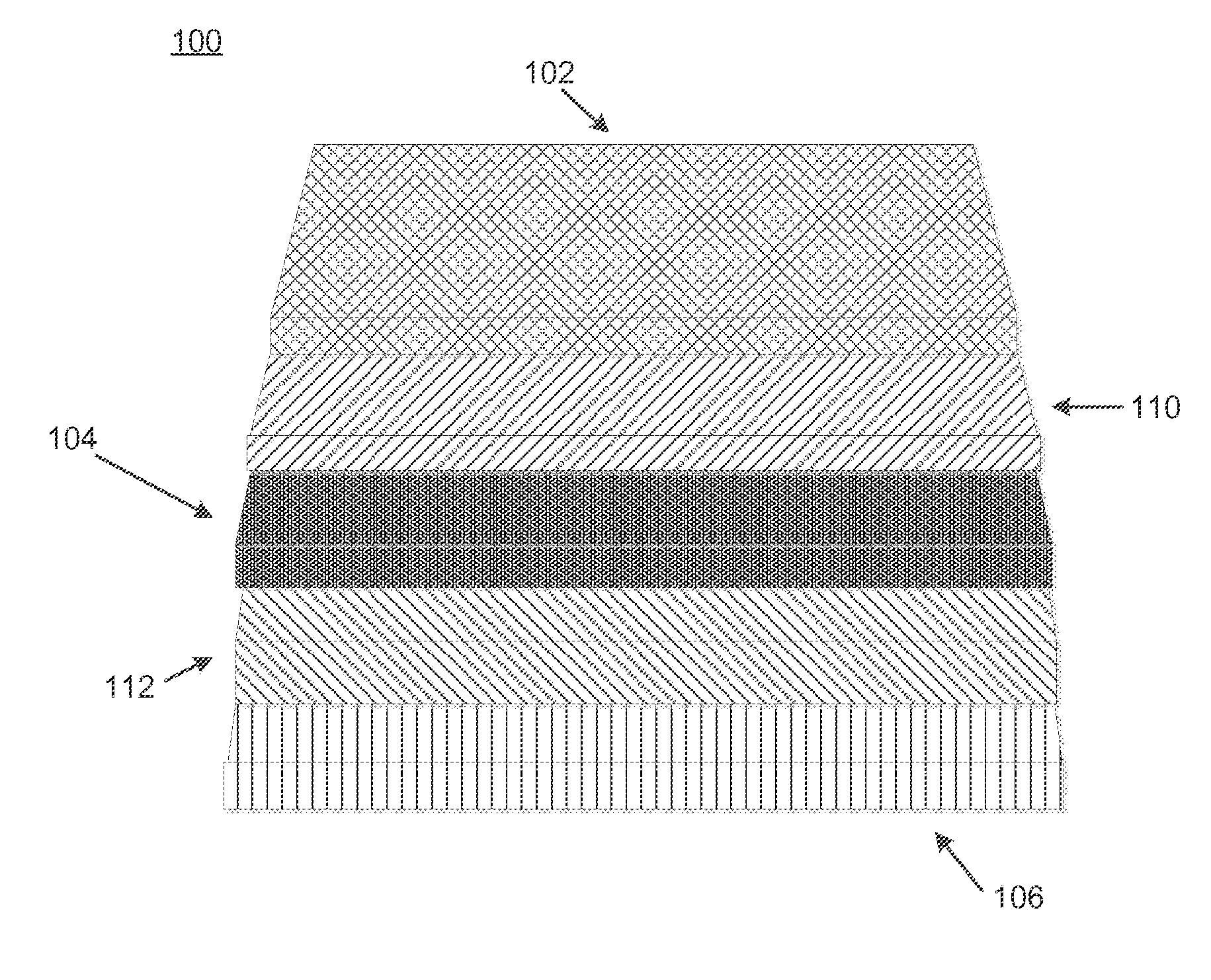
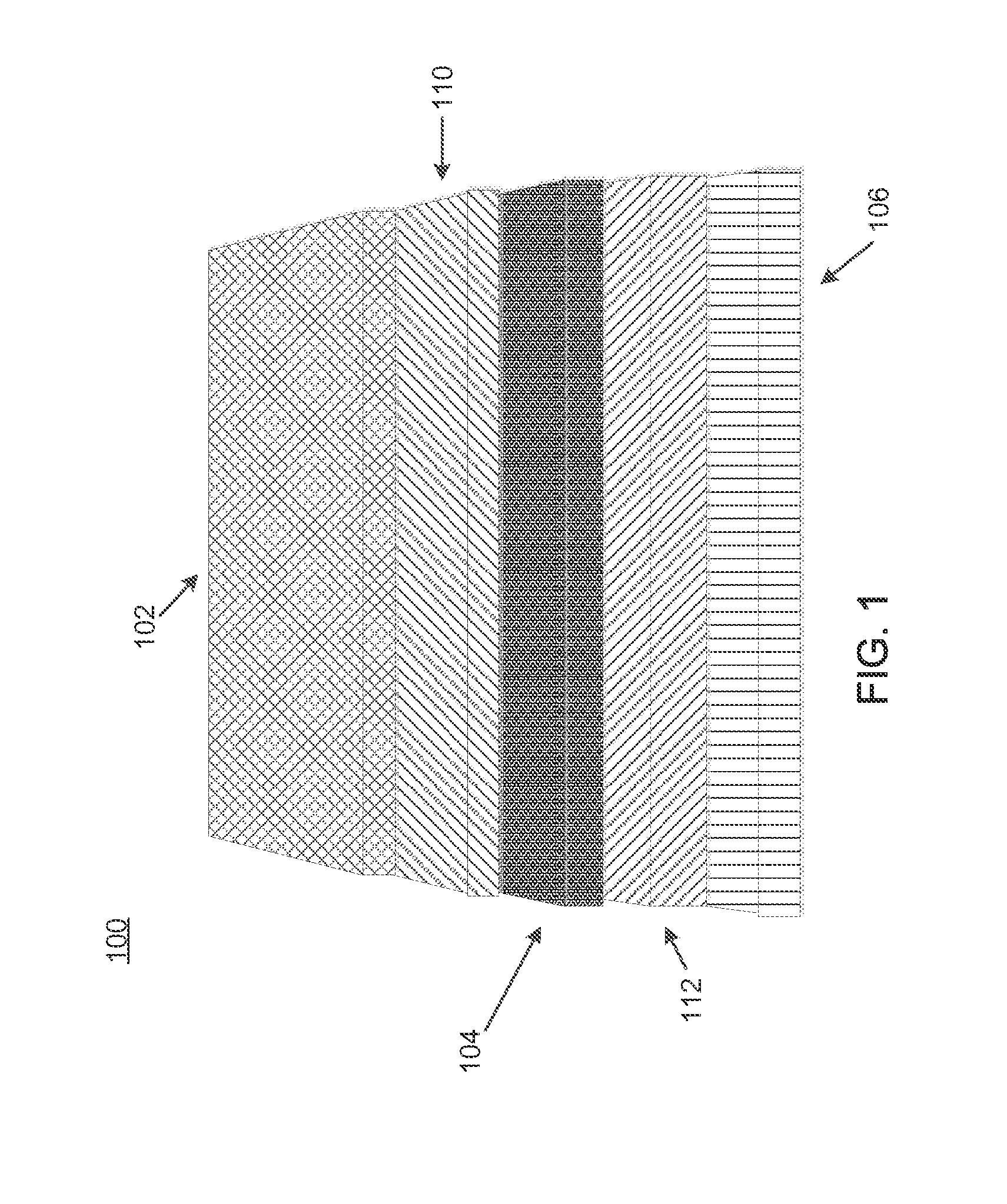
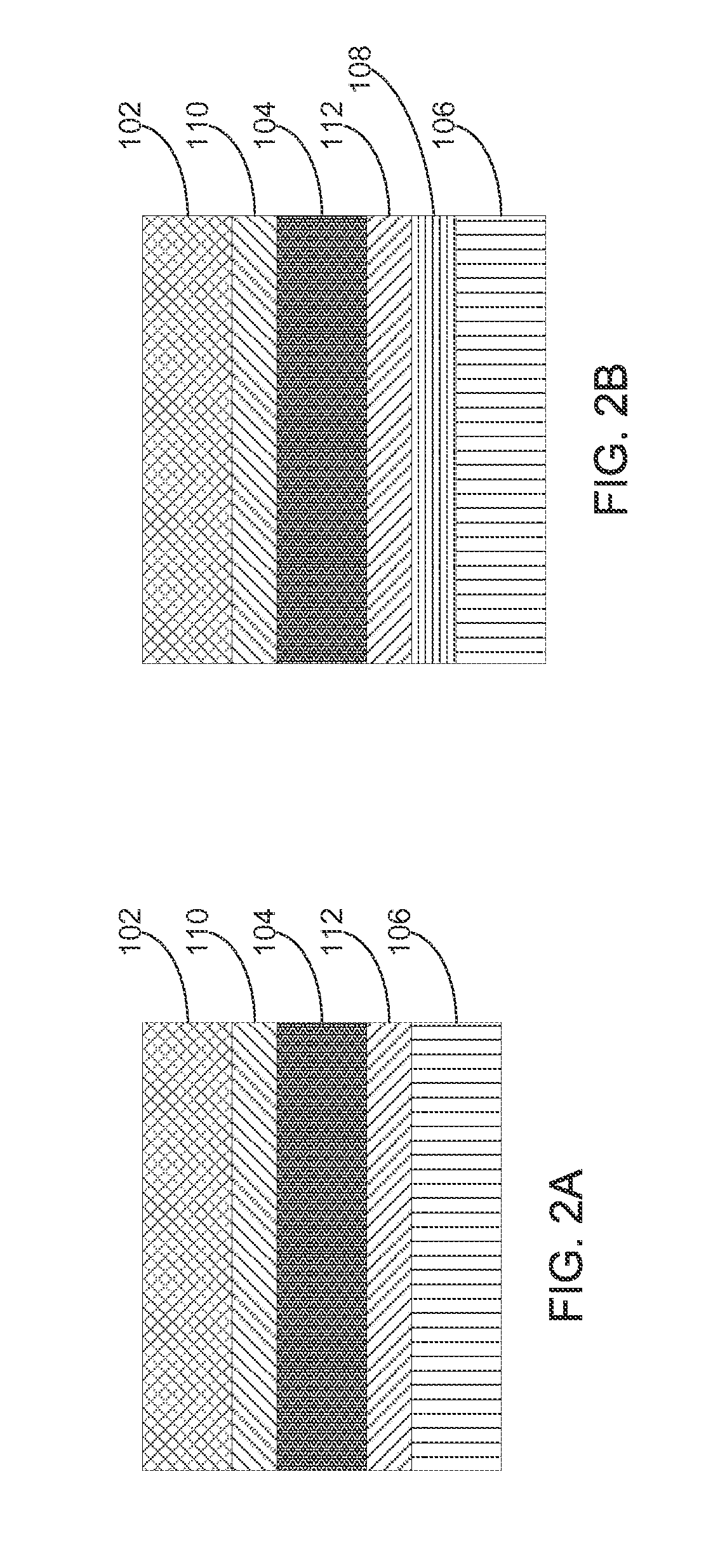
[0018]As shown in FIGS. 1 and 2A, an example flooring system 100 may include a top floor layer 102, a foam underlayment material 104, and a sub-floor 106. The top floor layer may include, for example, a laminate or hardwood flooring material. The underlayment material 104, which is described in detail herein, may be, for example, a foam underlayment material such as, the FloorMuffler™, which is manufactured by Toray Plastics (America), Inc. and distributed by Diversified Foam Products, Inc. (www.floormuffler.com). The sub-floor 106 may be a wood or concrete sub-floor, for example. It should be understood that the sub-floor 106 might be a previously-installed flooring system, for example, that is to be covered over, or any support structure, such as a system of floor joists, for example, on which the top layer 102 and underlayment material are installed to form a flooring system.

[0019]The layers 102, 104, and 106 may be affixed to one another by any practicable means. For example, th...


PUM

PropertyMeasurementUnit
densityaaaaaaaaaa
frequencyaaaaaaaaaa
densityaaaaaaaaaa

Abstract

A flooring system having a top floor layer, a sub-floor, and an underlayment material disposed between the sub-floor and the top floor layer is disclosed. The underlayment material may include a cross-linked, polyolefin foam having a moisture vapor transmission rate of less than about 3.0 lb / 1000 ft2 / 24 hr, and an average sound pressure level of less than about 15 dB over a range of about 300 Hz to about 1000 Hz. Foam density, gel fraction, and resin blend may combine to provide an underlayment material having such reflective sound and moisture vapor barrier properties.

Description

CROSS-REFERENCE TO RELATED APPLICATIONS[0001]This application is a continuation of U.S. patent application Ser. No. 11 / 261,977, filed Oct. 28, 2005, which claims benefit under 35 U.S.C. §119(e) of provisional U.S. patent application No. 60 / 622,764, filed Oct. 28, 2004, the disclosures of each of which are incorporated herein in their entireties.BACKGROUND OF THE INVENTION[0002]A typical hardwood, laminate, or engineered flooring system may include two or more layers. A top layer typically details the pattern and texture of the product, and may include a protective layer, such as a hard coating, for durability. A core layer may be prepared from pressed fiberboard, for example, or from other suitable materials. A bottom layer may be included to stabilize the product and to protect it from deleterious effects of moisture. Frequently, laminate or engineered flooring systems employ some type of tongue and groove design to allow the pieces of the flooring to bond together without requirin...

Claims


Application Information

Patent Timeline
Patent Type & Authority Applications(United States)
IPC IPC(8): B32B3/26
CPCB29K2023/00E04F15/203B32B5/022B32B5/245B32B5/32B32B15/08B32B21/047B32B21/08B32B21/14B32B2266/025B32B2307/102B32B2307/718B32B2307/7246B32B2419/04E04F15/18B32B3/30E04F15/186E04F15/182Y10T428/249953E04F15/206
Inventor KEANE, CRAIG PATRICK
Owner DIVERSIFIED FOAM PRODS
Why Eureka
Try Eureka