Axial flow fan

An axial flow, fan technology, applied in the field of rib shape

Active Publication Date: 2007-06-27
NIDEC CORP
View PDF0 Cites 10 Cited by
  • Summary
  • Abstract
  • Description
  • Claims
  • Application Information

AI Technical Summary

Problems solved by technology

Additionally, the airflow interferes with the ribs causing interference noise, a source of noise in fans

Method used


Image

  • Axial flow fan
  • Axial flow fan
  • Axial flow fan

Examples


Embodiment Construction

[0029] A preferred embodiment of the present invention will be described in detail with reference to FIGS. 1 to 12C. It should be noted that in the description of the present invention, when the positional relationship and orientation between different components are described as up / down or left / right, it refers to the final positional relationship and orientation in the drawings; The positional relationship and orientation of parts when assembled into an actual device. Meanwhile, in the following description, an axial direction refers to a direction parallel to a rotation shaft, and a radial direction refers to a direction perpendicular to the rotation shaft.

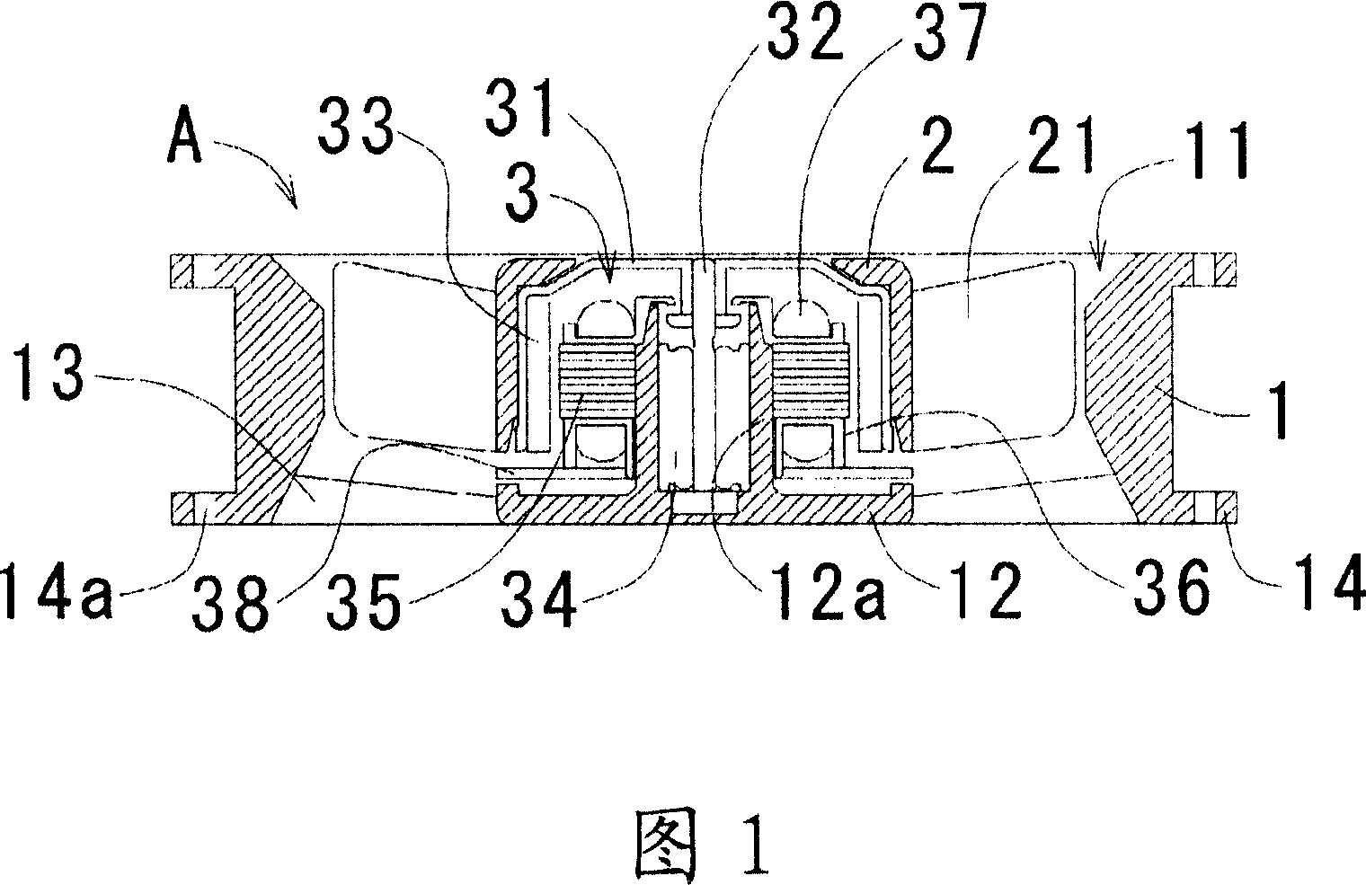
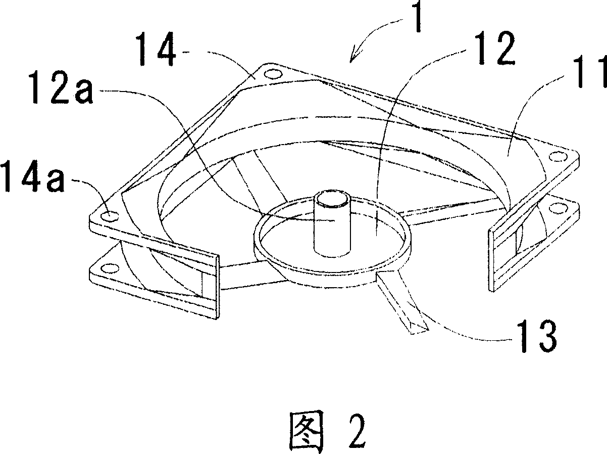
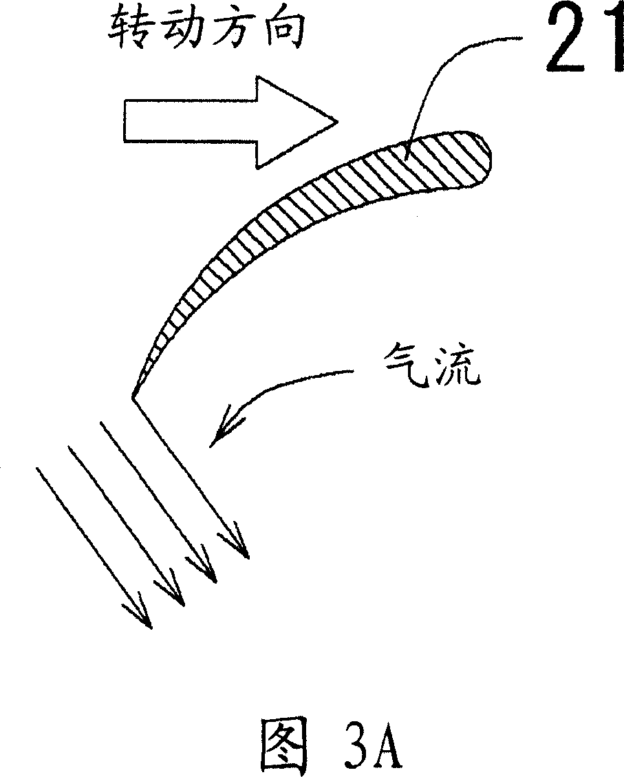
[0030] FIG. 1 is a cross-sectional view of an axial fan according to an exemplary embodiment of the present invention. FIG. 2 is a perspective view of the casing of the axial fan in FIG. 1 . FIG. 3A shows the cross-sectional shape of the impeller blade viewed in the radial direction, and the direction of rotation of ...


PUM


Abstract

An axial flow fan includes a motor placed on a frame and including a rotor rotatable around a rotation axis. An impeller is attached to an outer circumference of the rotor to rotate around the rotation axis and includes blades for generating an air flow when the rotor rotates. A housing surrounds the impeller to form a passage for the air flow. Ribs extend from the frame to the housing, thereby securing the frame to the housing. Each rib includes an air guide face which faces the impeller. An angle of average inclination of the air guide face with respect to the rotation axis decreases in a direction away from the rotation axis. The average inclination of the air guide face is defined as inclination of a straight line approximately connecting both ends of the air guide face on a plane perpendicular to a radial direction.

Description

technical field [0001] The present invention relates to an axial fan, and more particularly, to a shape of a rib in the axial fan. Background technique [0002] Currently, electronic equipment is provided with many cooling fans for dissipating heat generated in the electronic equipment. As the performance of electronic equipment increases, the heat generated gradually increases, so the requirements for the cooling performance of the fan also become higher. In order to improve the cooling performance of the fan, it is necessary to improve the flow velocity characteristic and the static pressure characteristic of the fan. The improvement of these two characteristics requires the fan to rotate at a high speed. On the other hand, with the increase of electronic devices used in homes or offices, there is an increasing demand for noise reduction in many electronic devices. [0003] A general fan includes: a motor; an impeller having a plurality of blades mounted to a rotor of t...

Claims


Application Information

Patent Timeline
Patent Type & Authority Applications(China)
IPC IPC(8): F04D29/66F04D29/52F04D29/54F04D19/00
CPCF04D29/547F04D29/582F04D25/0613F04D29/544
Inventor 吉田裕亮
Owner NIDEC CORP
Why Eureka
Try Eureka