Electric fan

a technology of electric fans and fan blades, applied in the direction of machines/engines, stators, liquid fuel engines, etc., can solve the problems of screw loosening, falling down, and losing its function, and achieve the effect of better blowing

Inactive Publication Date: 2006-04-13
LEE MING TSUNG
View PDF4 Cites 7 Cited by
  • Summary
  • Abstract
  • Description
  • Claims
  • Application Information

AI Technical Summary

Benefits of technology

[0005] The purpose of the invention is offer an electric fan possible to adjust the blowing angles and having a design for breaking through the conventional shape for carrying out better blowing effect.

Problems solved by technology

Further, conventional electric fans can change the up-and-down angles of the head and the swing angles to the right and left by means of a support rod and a bolt, but the screw may often become loose and fall down to lose its function.

Method used


Image

  • Electric fan
  • Electric fan
  • Electric fan

Examples


Embodiment Construction

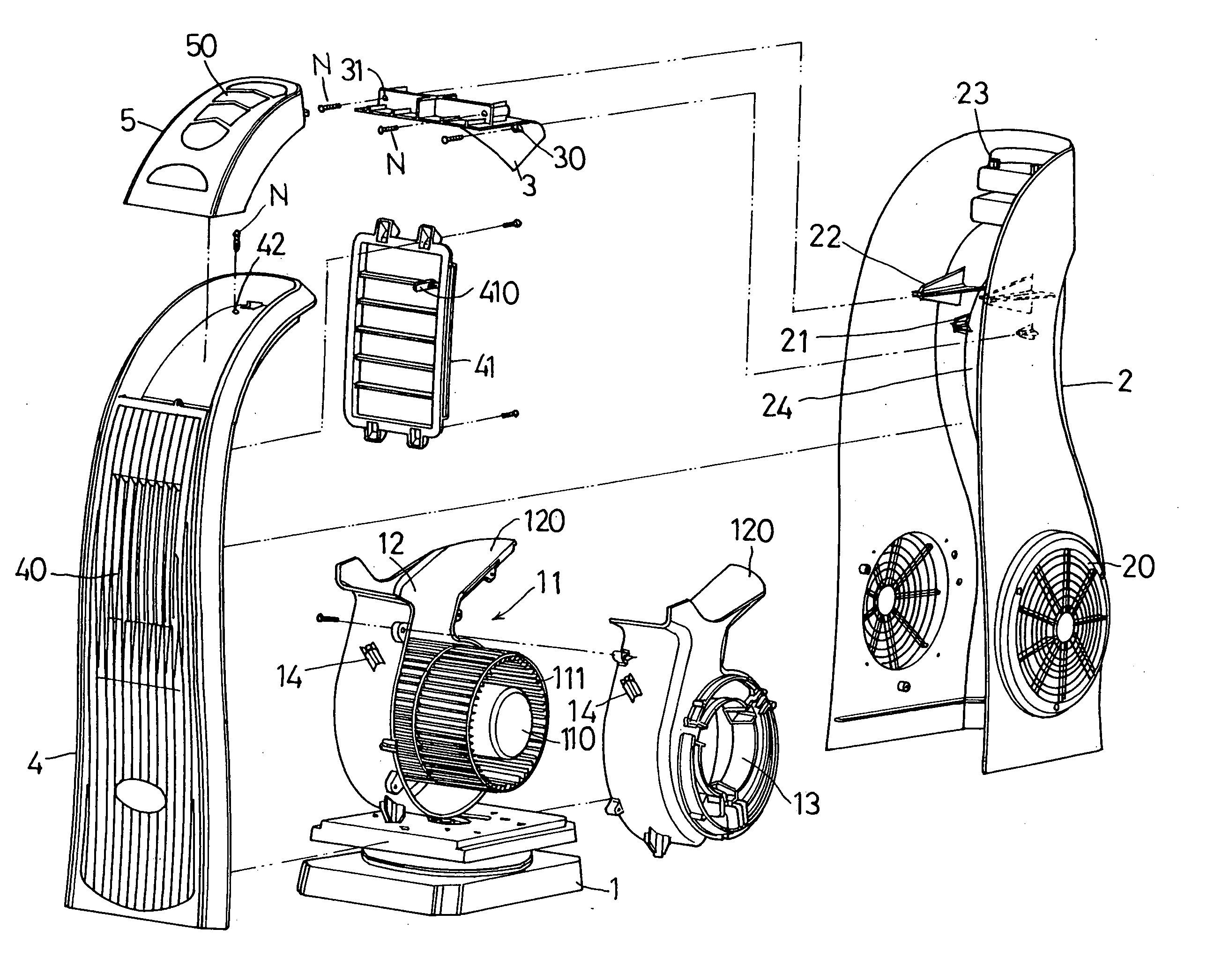
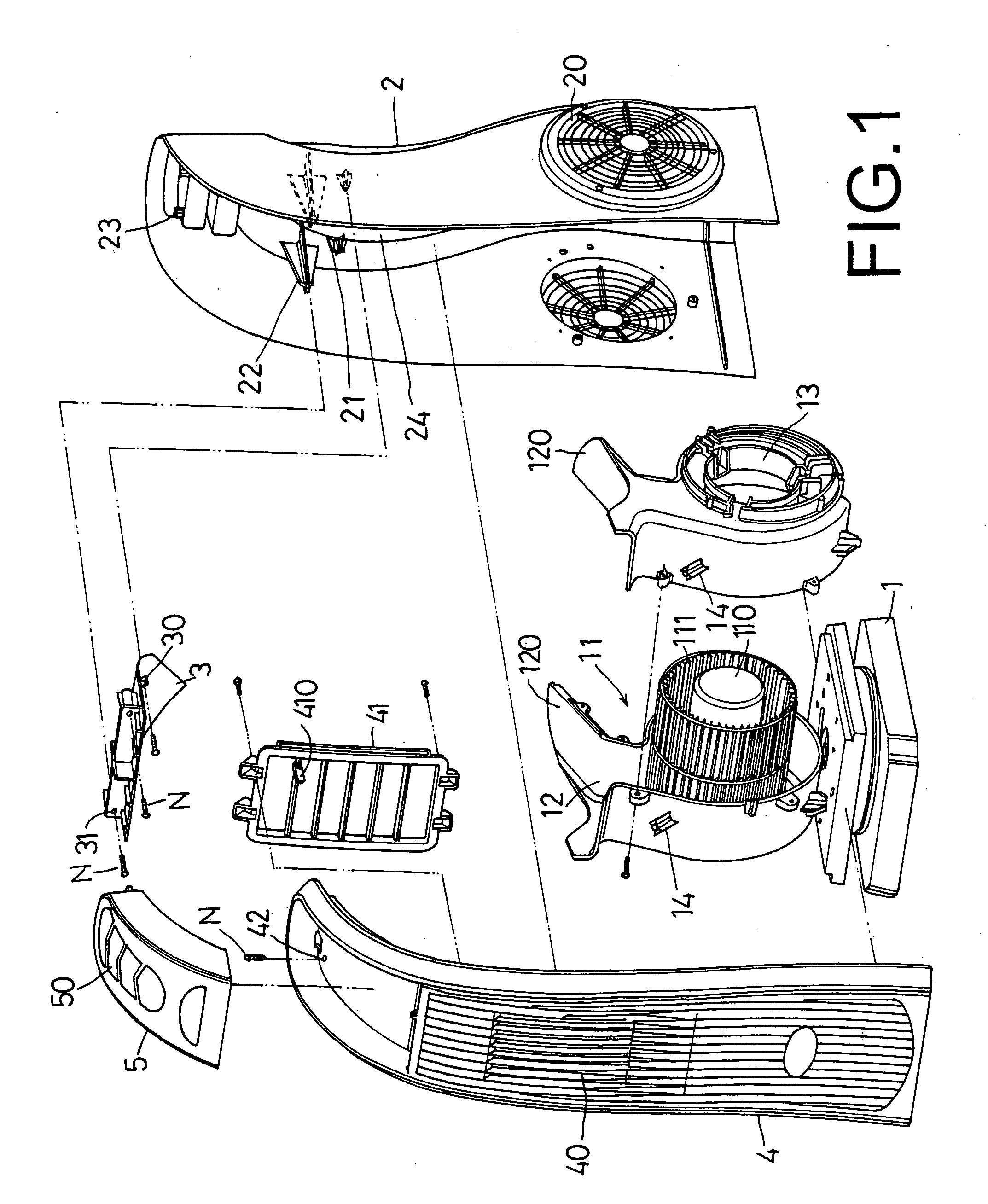
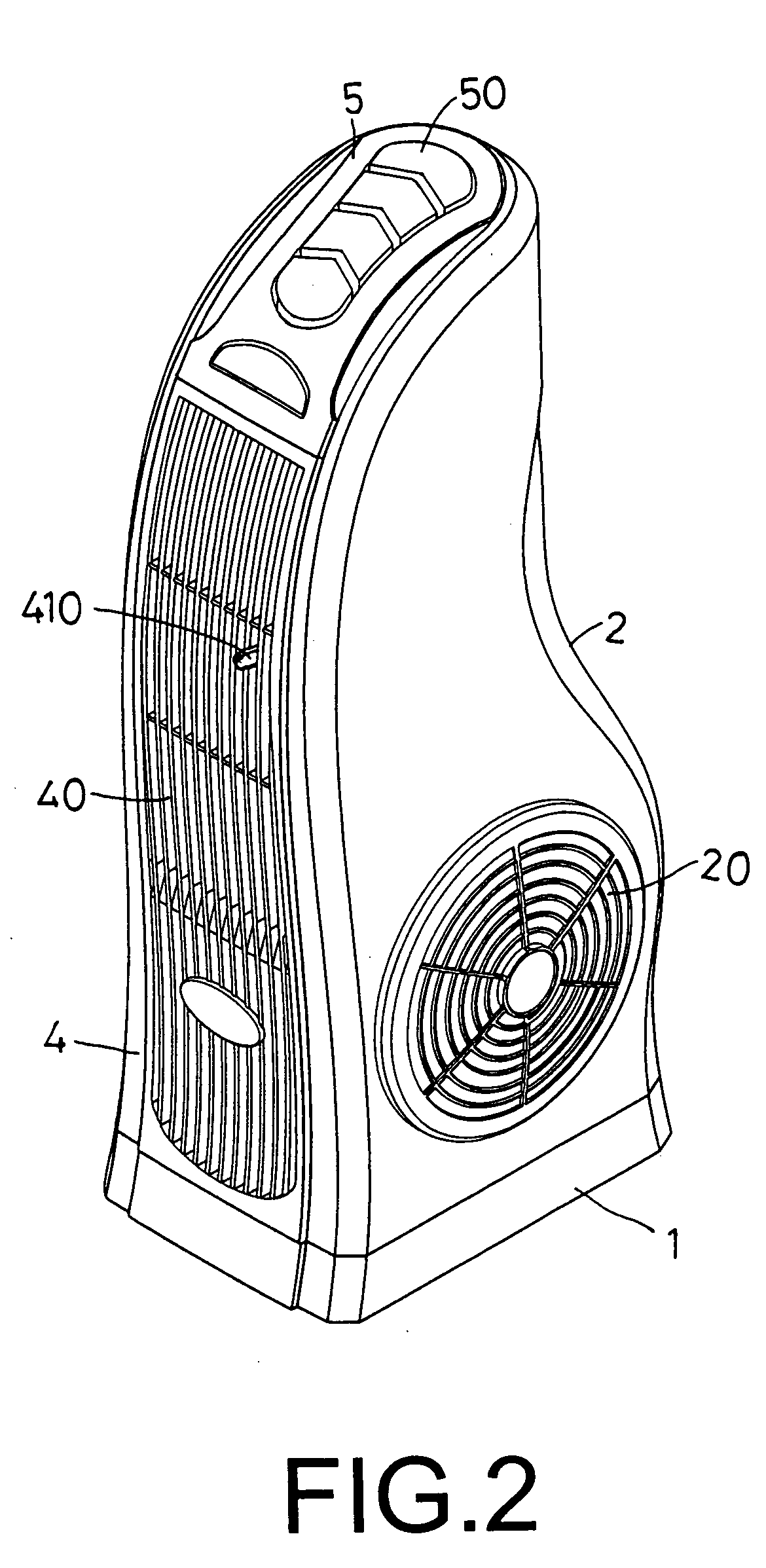
[0013] A preferred embodiment of an electric fan in the present invention, as shown in FIGS. 1, 2, 3 and 4, includes a base 1, a turbine fan 11, a housing 2, a guide plate 3, a front cover 4, an upper cap 5, as main components combined together.

[0014] The turbine fan 11 has a motor 110 installed on the base 11 and possible to change its directions, a set of leaves 11, a wind passageway 12 formed in an upper portion, a sloped guide surface 120 extending sloping upward from the wind passage 12, a wind inlet 13 respectively formed in the two sides, and a combine post 14 formed on a front side surface.

[0015] The housing 2 is combined on the base 1, shaped nearly as U, surrounding the two sides and a rear side of the turbine fan 11, having plural grid inlets 20 formed in the two sides and facing the wind inlet 13 of the turbine fan 11, and plural combine posts 21, 22 and 23 formed on an upper inner surface and a curved surface 24 on the rear side.

[0016] The guide plate 3 is fixed on t...


PUM


Abstract

An electric fan includes a base; a turbine fan fixed on the base; a housing installed on the base; a guide plate; a front cover in the front side of the housing; and an upper cap on top of the front cover. The turbine fan has a wind passage, a sloped guide surface, and two wind inlets in two sides. The housing has grid inlets facing the wind inlets of the turbine fan and a curved surface. The guide plate is fixed on the curved surface of the housing. The front cover has grid outlets and adjust leaves. When the turbine fan operates, air is sucked in through the grid inlets of the housing, the wind inlets and out of the wind outlets, guided by the sloped guide surface, the curved surface of the housing, blown out of the grid outlets of the front cover in changeable directions.

Description

BACKGROUND OF THE INVENTION [0001] 1. Field of the Invention [0002] This invention relates to an electric fan, particularly to one adjustable in blowing directions to an upper and a lower angle by means of an adjustable leaves set of a front cover deposited on a front cover closing on a front side of a housing surrounding a turbine fan fixed on a base. When the turbine fan consisting of a motor and a fan leaves set is operated, air is sucked in the housing though grid wind holes, and then through the wind inlets and along the wind passageway of the turbine fan, and along the curved surface of the housing and a guide plate in the housing and finally out of the grid wind holes of the front cover into an upper and a lower direction adjusted by the adjust leaves set. [0003] 2. Description of the Prior Art [0004] Common conventional electrical fans have a motor, a set of fan leaves to be rotated by the shaft of the motor for the leaves to generate wind for cooling, and their shapes are m...

Claims


Application Information

Patent Timeline
Patent Type & Authority Applications(United States)
IPC IPC(8): F04D29/44
CPCF04D29/424F04D29/626
Inventor LEE, MING-TSUNG
Owner LEE MING TSUNG
Why Eureka
Try Eureka