Hammer tool

一种打击工具、工具的技术,应用在打击工具、轻便冲击工具、制造工具等方向,能够解决回转数降低、打击次数从极限打击次数降低、打击构件打击效率降低等问题,达到提高效率的效果

Active Publication Date: 2010-03-24
MAX CO LTD
View PDF2 Cites 9 Cited by
  • Summary
  • Abstract
  • Description
  • Claims
  • Application Information

AI Technical Summary

Problems solved by technology

[0008] In addition, for a rechargeable tool, during operation, the battery voltage of the motor of the tool is lowered and thus the number of revolutions of the motor is lowered, whereby the number of strikes of the tool is greatly reduced from the limit number of strikes, and thus the striking efficiency of the striking member is also reduced.

Method used


Image

  • Hammer tool
  • Hammer tool
  • Hammer tool

Examples


Embodiment Construction

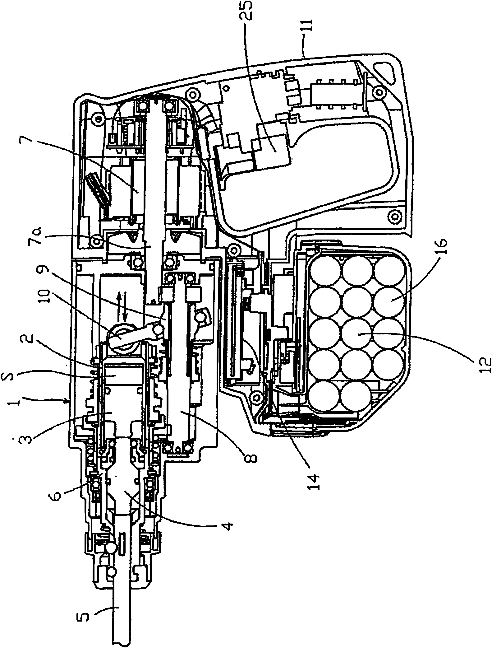
[0026] figure 1 It is a longitudinal sectional view of the main part of the hammer drill. exist figure 1 In , reference numeral 1 indicates the tool body. The tool body 1 includes: a piston 2 with a cylindrical bottom, capable of reciprocating movement; a striking member 3, which is slidably arranged in the piston 2; an intermediate member 4, to which the striking force of the striking member 3 is transmitted, The striking member 3 is capable of performing its striking motion in conjunction with changes in the air pressure of the air chamber S formed between the piston 2 and the striking member 3 due to the back and forth reciprocating motion of the piston 2; Pass to the top tool 5. Piston 2 , intermediate member 4 and tip tool 5 are slidably accommodated in cylinder 6 .

[0027] The motor 7 is housed in the rear of the tool main body 1 , and the output shaft 7 a of the motor 7 engages with the intermediate shaft 8 in a meshing manner. A motion conversion member 9 is rota...


PUM


Abstract

A hammer tool has, in a tool body (1), a piston (2) reciprocated by drive force of a motor (7), a hammer element (3) for performing hammering operation in association with the reciprocation of the piston (2), and an intermediate element (4) for transmitting hammering force of the hammer element (3) to a head tool (5) inserted and attached to the head of the tool body. The tool body has a measurement device (13) for measuring the condition of hammering by the hammer element (3) and also has a control device for controlling the speed of the motor (7). The control device (13) determines, based onthe result on measurement by the measurement device (13), the limit number of times of hammering which makes the hammer element (3) unable to follow the reciprocation of the piston (2), and the control device controls the speed of the motor (7) according to the result of the determination.

Description

technical field [0001] The present invention relates to a striking tool that transmits the striking force of a striking member to a tip tool such as a drill bit or a point drill mounted on the tip of a main body of the striking tool so as to pierce or break concrete or stone. The member is able to perform its striking movement in conjunction with a piston that reciprocates when driven by a motor. Specifically, the present invention relates to an electric hammer, a hammer drill and the like. Background technique [0002] Generally, hammer drills are constructed such that a piston is driven by a motor to reciprocate back and forth on the shaft of the tip tool, thereby changing the air pressure of the air chamber formed between the piston and the striking member; thus, the change in air pressure (air spring) is used to The striking member is enabled to generate its striking motion. Also, the hammer drill transmits the striking force of the striking member to the tip tool thro...

Claims


Application Information

Patent Timeline
Patent Type & Authority Applications(China)
IPC IPC(8): B25D11/04
CPCB25D2211/061B25D2250/201B25D11/005B25D2250/221
Inventor 加藤浩二滨野晃史大塚功崇寺西明坂卷一弥
Owner MAX CO LTD
Why Eureka
Try Eureka