Three phase rectifier bridge active power filter circuit using impedance coupling

A technology of three-phase rectification and power filtering, applied in the direction of electrical components, output power conversion devices, etc., can solve the problems of application limitations, high circuit cost, etc., and achieve the effect of low cost, simple circuit, and a small number of active switches

Inactive Publication Date: 2007-06-27
CHONGQING UNIV
View PDF0 Cites 8 Cited by
  • Summary
  • Abstract
  • Description
  • Claims
  • Application Information

AI Technical Summary

Problems solved by technology

The power factor correction circuit needs to handle all the load power, and the active power filter is currently connected in parallel on the AC side. Both solutions use more high-frequency active switches, the circuit cost is high, and their practical applications are limited.
[0003] The active power filter circuit connected in parallel on the DC side of the rectifier bridge has been applied in the fields of high-voltage ...

Method used


Image

  • Three phase rectifier bridge active power filter circuit using impedance coupling
  • Three phase rectifier bridge active power filter circuit using impedance coupling
  • Three phase rectifier bridge active power filter circuit using impedance coupling

Examples


Embodiment Construction

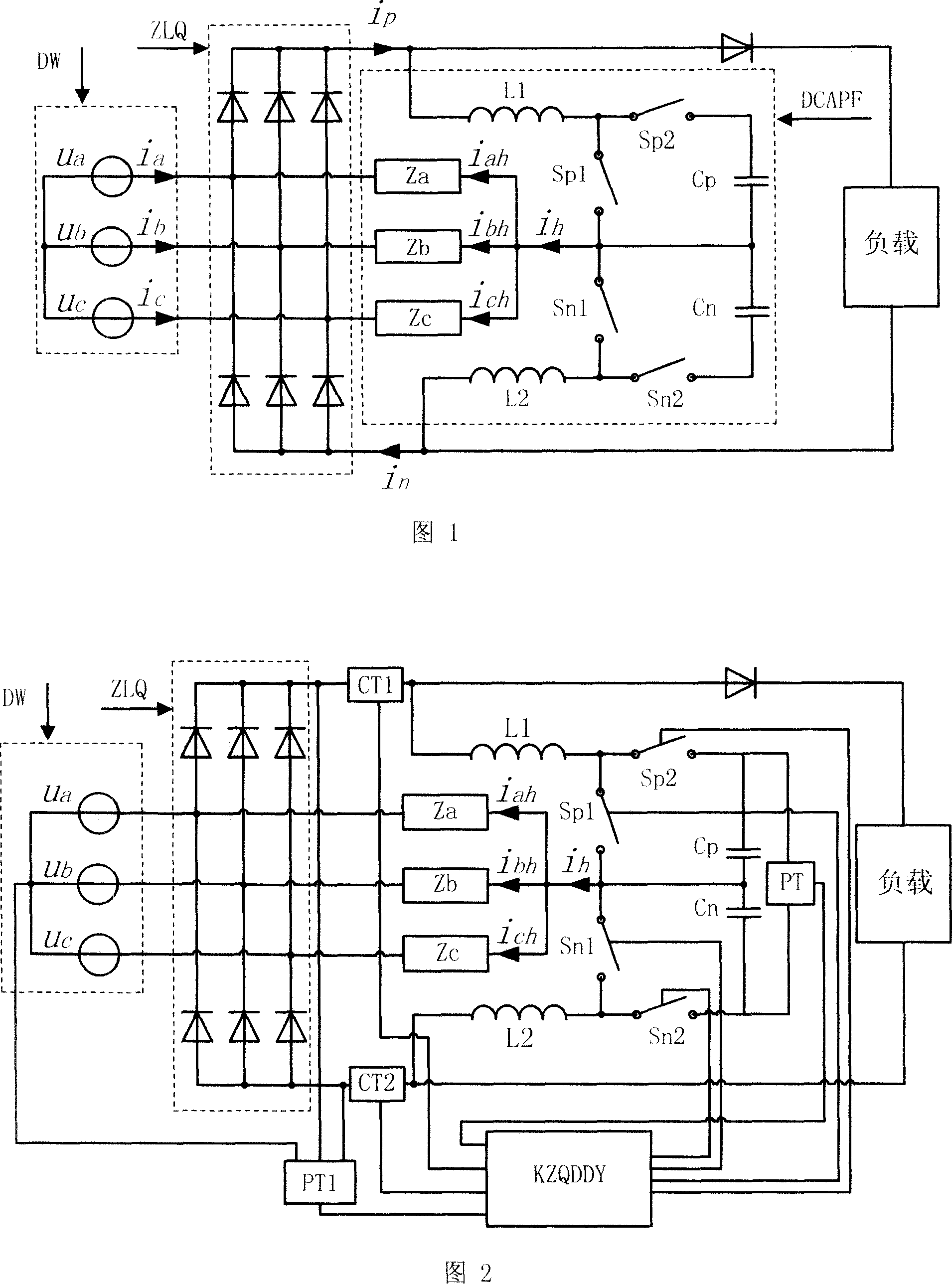
[0027] A three-phase rectifier bridge active power filter circuit using impedance coupling (refer to Figure 1). The filter circuit includes a bidirectional step-up power converter with a power switch tube, an impedance network and a control circuit. In the present invention, there are two bidirectional step-up power converters, each of which is composed of an inductance (L1, L2), a power switch tube (Sp2, Sn2) and a capacitor (Cp, Cn) connected in series in sequence. ), and another power switch tube (Sp1, Sn1) is tapped at the junction of the inductor (L1, L2) and the power switch tube (Sp2, Sn2). The two bidirectional boost power converters are connected in series by connecting two capacitors (Cp, Cn) and two tapped power switch tubes (Sp1, Sn1) to a common connection point; the common connection point It is connected to the AC side of the three-phase rectifier bridge ZLQ and the AC grid DW through three impedances (Za, Zb, Zc). The input ends of the two series connected bi...


PUM


Abstract

This invention relates to an active power filter circuit of a three-phase commutation bridge applying impedance couple including: a capacitor, an inductor, four power switch tubes and an impedance network, in which, the impedance network is connected at the three input ends of the three-phase comutation bridge,two serial two-way boosting power converters composed of capacitors, inductors and four power switch tubes are parallel at the DC side of the commutation bridge. This invention is especially suitable for treatment of harmonic waves loaded by a three-phase commutation bridge.

Description

technical field [0001] The invention belongs to the technical field of active power filters, in particular to a parallel active power filter. Background technique [0002] The three-phase rectifier bridge is a very widely used load in the power system, and it is also a major harmonic source that generates harmonics to the power system. Harmonic control of the three-phase rectifier bridge, power factor correction circuit and active power filter circuit are two main schemes currently used. The power factor correction circuit needs to handle all the load power, and the active power filter is currently connected in parallel on the AC side. Both solutions use more high-frequency active switches, and the circuit cost is high, so their practical applications are limited. [0003] The active power filter circuit connected in parallel on the DC side of the rectifier bridge has been applied in the fields of high-voltage DC transmission and special power supplies, but the active power...

Claims


Application Information

Patent Timeline
IPC IPC(8): H02M1/14
Inventor 杜雄周雒维卢伟国罗全明侯世英
Owner CHONGQING UNIV
Why Eureka
Try Eureka