Electric equipment protective device
A technology of electrical components and protection devices, applied in variable capacity pump components, pump components, liquid variable capacity machinery, etc., can solve problems such as bad, small gaps, leakage insulation, etc.
- Summary
- Abstract
- Description
- Claims
- Application Information
AI Technical Summary
Problems solved by technology
Method used
Image
Examples
Embodiment 1
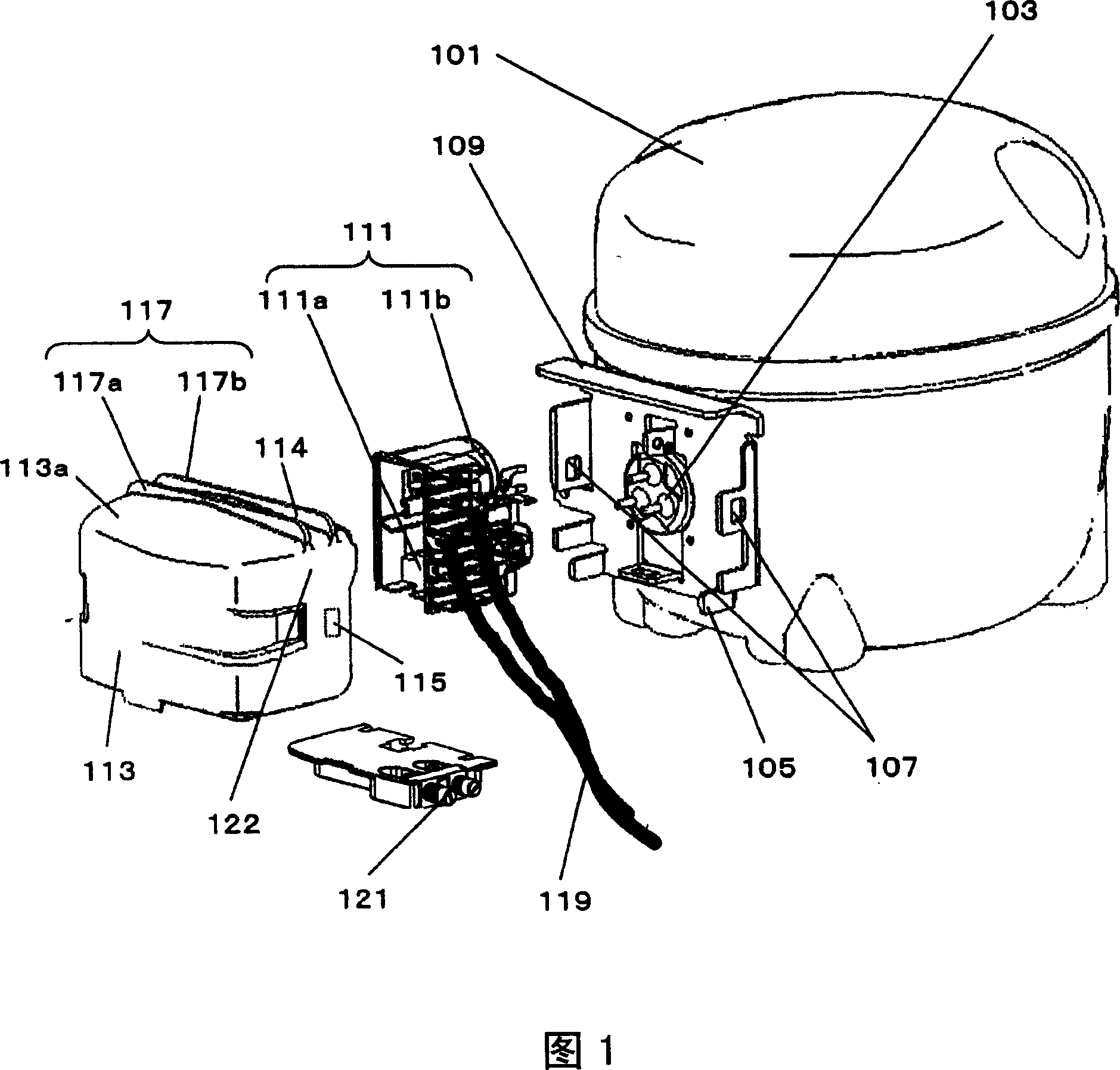
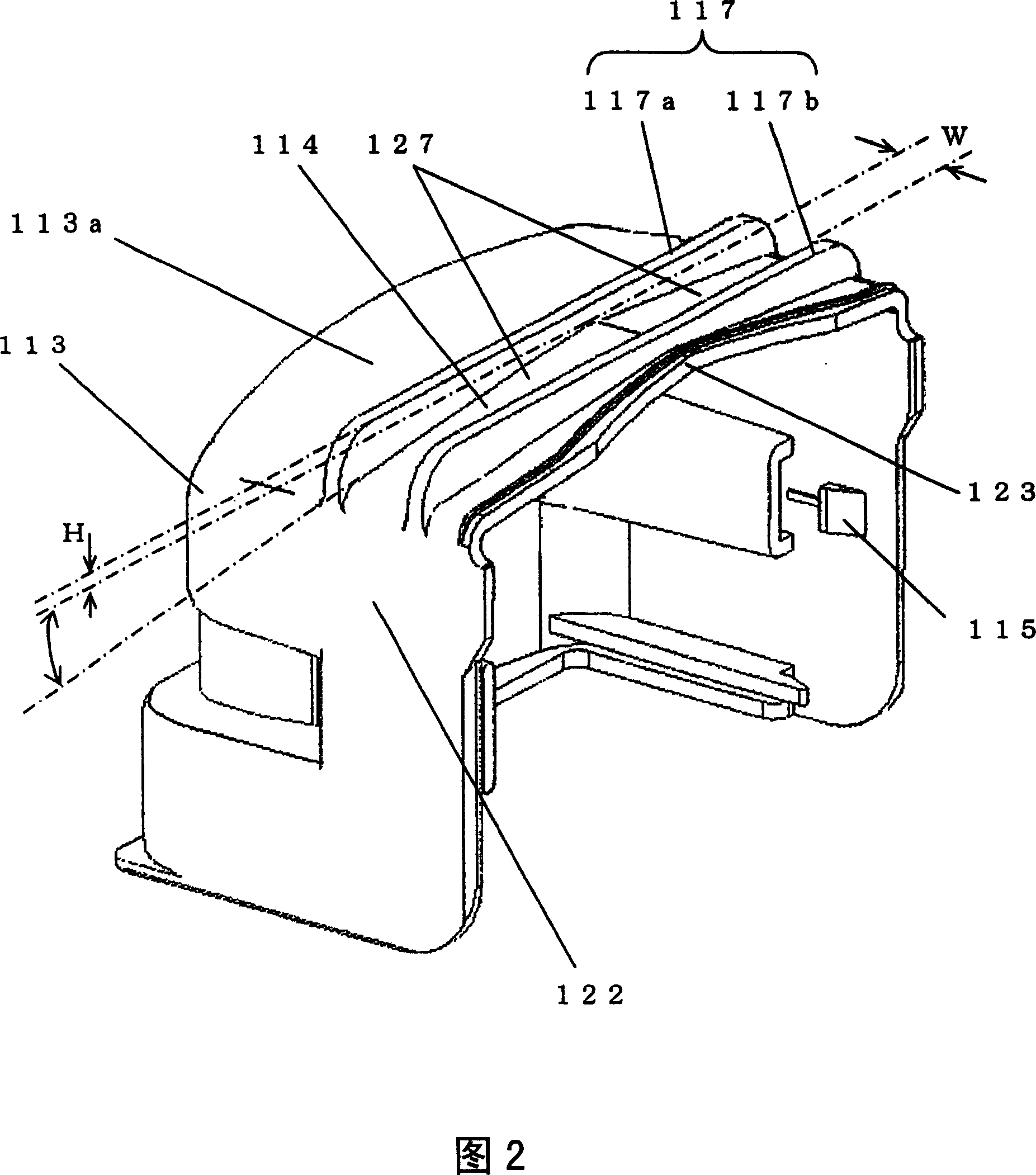
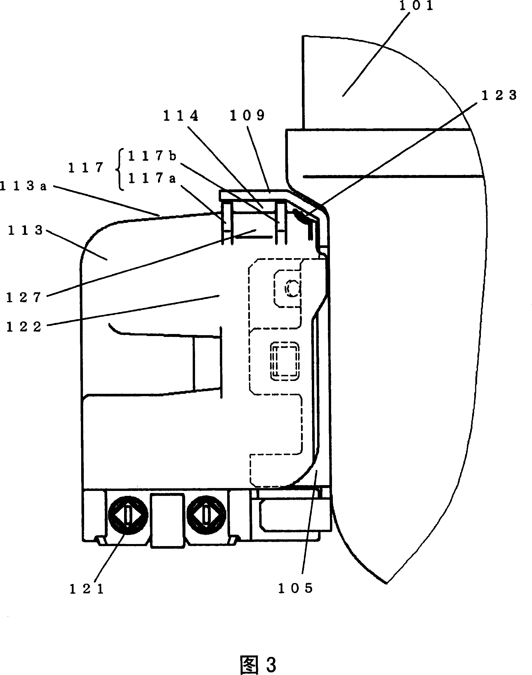
[0042] Fig. 1 is an exploded perspective view of the electrical component protection device in Embodiment 1 of the present invention, Fig. 2 is a perspective view of the electrical component cover, Fig. 3 is an enlarged schematic view of the electrical component protection device in an installed state, and Fig. 4 is a second Experimental results diagram of the experiment.
[0043] A motor mechanism (not shown in the figure) and a compression mechanism (not shown in the figure) driven by the motor mechanism are installed inside the compressor casing 101 .
[0044] As shown in FIGS. 1 to 3 , the electrical component 111 includes a starting relay 111 a and a motor protector 111 b. The purpose of using the starting relay 111a is to control the energization of the motor mechanism, so as to prevent the motor mechanism from being burned due to excessive current flowing.
[0045] Specifically, the motor mechanism is provided with a main winding (not shown in the figure) and an auxiliar...
Embodiment 2
[0080] Fig. 5 is an exploded perspective view of an electrical component protection device according to Embodiment 2 of the present invention, Fig. 6 is a perspective view of an electrical component cover, Fig. 7 is an enlarged schematic view of the electrical component protection device in an installed state, and Fig. 8 is a second Schematic diagram of the experimental results.
[0081] In FIGS. 5 to 7 , a motor mechanism (not shown in the figure) and a compression mechanism (not shown in the figure) driven by the motor mechanism are installed inside the compressor casing 201 .
[0082] The electrical components 211 include a starting relay 211a and a motor protector 211b. The purpose of using the starting relay 211a is to control the energization of the motor mechanism, so as to prevent the motor mechanism from being burned due to excessive current flowing.
[0083] Specifically, the motor mechanism is provided with a main winding (not shown in the figure) and an auxiliary ...
Embodiment 3
[0117] Fig. 9 is an exploded perspective view of the electrical component protection device in Embodiment 3 of the present invention, Fig. 10 is a perspective view of the electrical component cover, Fig. 11 is an enlarged schematic diagram of the electrical component protection device in an installed state, and Fig. 12 is along the diagram 11 is a cross-sectional view of line A-A, and FIG. 13 is a schematic diagram of the experimental results of the second experiment.
[0118] In FIGS. 9 to 12 , a motor mechanism (not shown in the figure) and a compression mechanism (not shown in the figure) driven by the motor mechanism are arranged inside the compressor casing 301 .
[0119] The electrical components 311 include a starting relay 311a and a motor protector 311b. The purpose of using the starting relay 311a is to control the energization of the motor mechanism, so as to prevent the motor mechanism from being burned due to excessive current flowing.
[0120] Specifically, the ...
PUM
| Property | Measurement | Unit |
|---|---|---|
| Groove depth | aaaaa | aaaaa |
| Groove width | aaaaa | aaaaa |
Abstract
Description
Claims
Application Information
 - R&D
- Intellectual Property
- Life Sciences
- Materials
- Tech Scout
- Unparalleled Data Quality
- Higher Quality Content
- 60% Fewer Hallucinations
Browse by: Latest US Patents, China's latest patents, Technical Efficacy Thesaurus, Application Domain, Technology Topic, Popular Technical Reports.
© 2025 PatSnap. All rights reserved.Legal|Privacy policy|Modern Slavery Act Transparency Statement|Sitemap|About US| Contact US: help@patsnap.com


