Double-cylinder rotary sealing type compressor and manufacturing method thereof
A rotary and hermetic technology, applied in the direction of pump combination, machine/engine, mechanical equipment, etc. for elastic fluid rotary piston type/oscillating piston type, which can solve distortion, compression power reduction, leakage loss or sliding loss Increase and other problems, to achieve the effect of reducing distortion, high compression power, and reducing leakage loss
- Summary
- Abstract
- Description
- Claims
- Application Information
AI Technical Summary
Problems solved by technology
Method used
Image
Examples
no. 1 approach
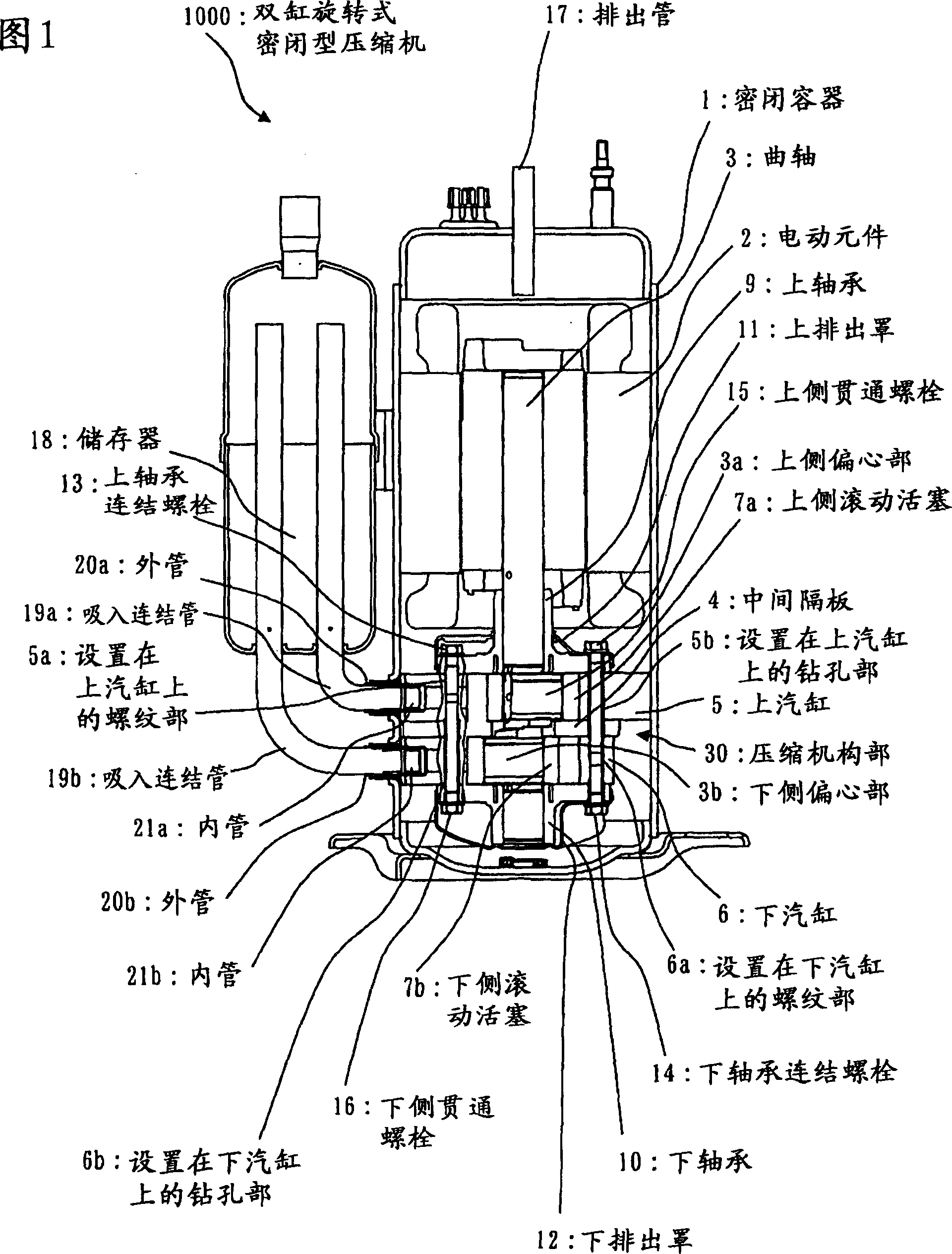
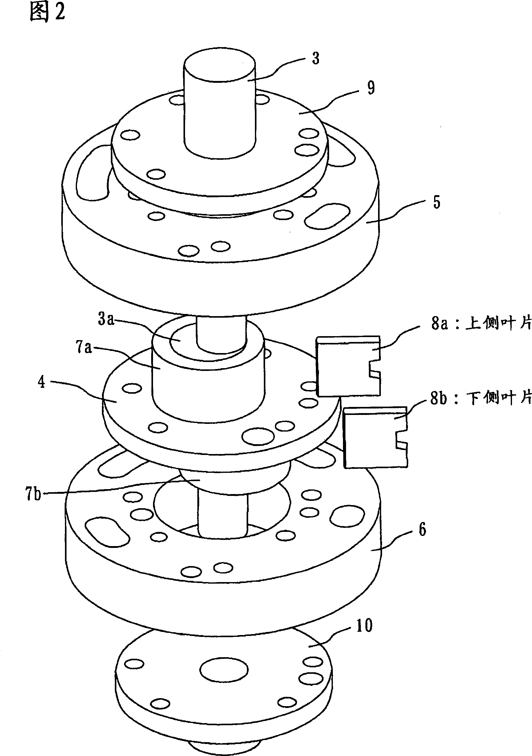
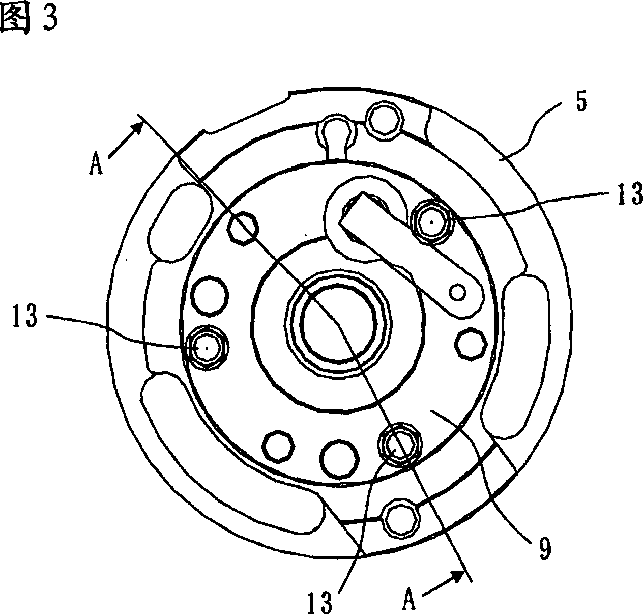
[0030] 1 to 15 are diagrams showing the first embodiment. FIG. 1 is a longitudinal sectional view showing a two-cylinder rotary hermetic compressor 1000; FIG. An exploded perspective view; FIG. 3 is a top view showing that the upper bearing 9 is fixed on the upper cylinder 5 with the upper bearing connecting bolt 13; FIG. 4 is a sectional view showing the A-A line of FIG. 3; FIG. 10 is fixed on the top view of the lower cylinder 6; Fig. 6 is a sectional view showing the B-B line of Fig. 5; Fig. 7 is a sectional view showing the assembly of the upper cylinder 5, and the lower cylinder 6 and the lower bearing 10 are unassembled compression mechanism parts; Fig. 8 It is a plan view showing the state before the lower cylinder 6 and the lower bearing 10 are installed, that is, the lower bearing 10, the lower cylinder 6, and the intermediate partition plate 4 are connected to the upper cylinder 5 with the lower through bolts 16; FIG. Figure 10 is a sectional view showing the upper d...
no. 2 approach
[0052] FIG. 16 is a diagram showing a second embodiment, and is a vertical cross-sectional view of a two-cylinder rotary hermetic compressor 2000 .
[0053] As shown in FIG. 16 , in the twin-cylinder rotary hermetic compressor 2000 of this embodiment, one suction connection pipe 19 is connected from the accumulator 18 to the suction port of the upper cylinder 5 or the lower cylinder 6 . In the example of FIG. 16 , the suction connecting pipe 19 is connected to the suction port of the upper cylinder 5 .
[0054] The assembly procedure of the compression mechanism unit 30 is the same as that of the first embodiment. When assembling the two-cylinder rotary hermetic compressor 2000, insert the compression mechanism part 30 and the electric element 2 into the airtight container 1, then insert the outer tube 20 into the suction port of the upper cylinder 5, and press the inner tube 21 into it. . Thereafter, the suction connection pipe 19 from the reservoir 18 is inserted into the ...
no. 3 approach
[0063] 17 and 18 are diagrams of the third embodiment, and are cross-sectional views of main parts of the compression mechanism unit 30 .
[0064] As shown in the first embodiment and the second embodiment, since the compression mechanism part 30 is connected by each bolt, the inner diameter grinding part or the plane grinding part of the upper cylinder 5 and the lower cylinder 6 is distorted and deformed, thereby reducing the roundness, Therefore, leakage loss or sliding loss may increase.
[0065] Therefore, in order to reduce distortion of the inner diameter grinding portion, release portions (escape portions) are provided on the end faces of the threaded portion 5a and the threaded portion 6a, which are provided in the first embodiment and the second embodiment. On the upper cylinder of the two-cylinder rotary hermetic compressor, the threaded part 6a is arranged on the lower cylinder.
[0066] As shown in Fig. 17, once the upper cylinder 5 and the upper bearing 9 are fix...
PUM
 Abstract
Description
Claims
Application Information
 - R&D
- Intellectual Property
- Life Sciences
- Materials
- Tech Scout
- Unparalleled Data Quality
- Higher Quality Content
- 60% Fewer Hallucinations
Browse by: Latest US Patents, China's latest patents, Technical Efficacy Thesaurus, Application Domain, Technology Topic, Popular Technical Reports.
© 2025 PatSnap. All rights reserved.Legal|Privacy policy|Modern Slavery Act Transparency Statement|Sitemap|About US| Contact US: help@patsnap.com


