Centrifugal clutch

A centrifugal clutch and clutch plate technology, applied in clutches, automatic clutches, mechanical equipment, etc., can solve the problems of complex mechanism, difficult adjustment, increased cost, etc., and achieve the effect of firm fixed state, durability and low price.

Inactive Publication Date: 2007-07-04
YAMADA SEISAKUSHO KK
View PDF1 Cites 7 Cited by
  • Summary
  • Abstract
  • Description
  • Claims
  • Application Information

AI Technical Summary

Problems solved by technology

If the number of centrifugal hammers is set to be more than 3, the average weight of each centrifugal hammer can be reduced, and the force acting on the clutch housing is also distributed from two parts to three parts, which can reduce strain and reduce the resulting load. The vibration is good in terms of function, but compared with the case where the number of centrifugal hammers is set to two, there is a problem that the mechanism is complicated, the adjustment is difficult, and the cost increases

Method used


Image

  • Centrifugal clutch
  • Centrifugal clutch
  • Centrifugal clutch

Examples


Embodiment Construction

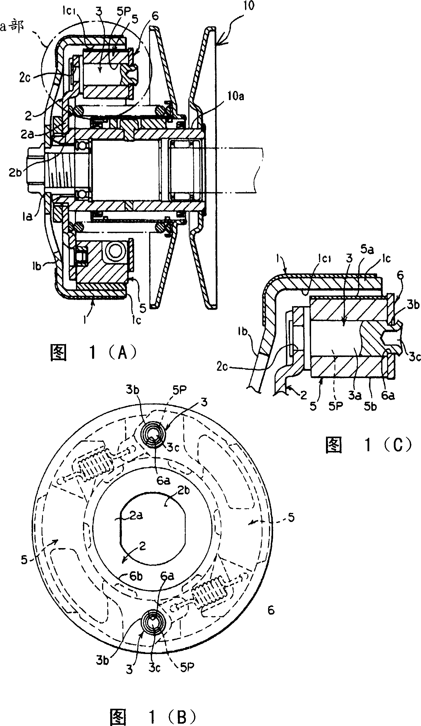
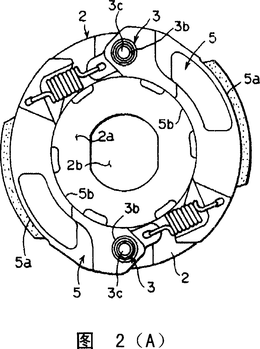
[0024] Embodiments of the present invention will be described below based on the drawings. Fig. 1 is an enlarged cross-sectional view of a centrifugal clutch connected to a continuously variable transmission of the present invention and its main parts. The centrifugal clutch of the present invention, as shown in Figure 1(A), is used together with continuously variable transmissions that share the same shaft mechanism and are adjacently arranged to disconnect / disconnect the driving force transmitted through the continuously variable transmission in vehicles such as motorcycles and the like. connected function. The centrifugal clutch is mainly composed of a clutch housing 1, a clutch plate 2, a centrifugal hammer 5 and the like. A device connected to this centrifugal clutch is a driven-side speed change pulley 10 (see FIG. 1(A)), which is of a variable pulley groove width. The driven side speed change pulley 10 is rotated by a driving side speed change pulley (not shown) via a...


PUM


Abstract

The object of the invention is to minimize the number of the centrifugal hammers of the belt-type continuously variable centrifugal clutch used for automatic two-wheel vehicle and so on. The centrifugal clutch of the invention is equipped with no more than three centrifugal hammers 5 which are installed at the peripheral portion of a substantially round clutch plate 2 by support pins 3 thereby being able to freely swing and which transfers the rotation to a clutch housing 1; and a side plate 6 which forms through holes 6a for being completely inserted by the terminal part of the support pins 3 and which is set above the centrifugal hammers 5 in the manner of covering the centrifugal hammers 5. The terminal part of the support pins 3 insert through the through holes 6a of the side plate 6 to be fixed.

Description

technical field [0001] The present invention relates to a centrifugal clutch capable of minimizing the number of centrifugal hammers in belt-type continuously variable transmissions of motorcycles and the like. Background technique [0002] Among the continuously variable transmissions, there is a continuously variable transmission in which a fixed pulley half and a movable pulley half that can move forward and backward relative to the fixed pulley half are respectively provided on the driving shaft and the driven shaft. The driving pulley is composed of an endless V-shaped belt wound between the driving shaft and the driving pulley on the driven shaft, and the rotation of the driving shaft is controlled by moving and adjusting the half body of the movable pulley on the driving shaft and the driven shaft. The rotation of the driven shaft and the driven shaft is continuously variable and transmitted to the driven shaft. In such a transmission, the driven pulley and the drive...

Claims


Application Information

Patent Timeline
Patent Type & Authority Applications(China)
IPC IPC(8): F16D43/18
CPCF16D2043/145F16D43/18
Inventor 川岛芳德渡边学道木正之
Owner YAMADA SEISAKUSHO KK
Why Eureka
Try Eureka