Supercharge Your Innovation With Domain-Expert AI Agents!

Method for operating an injection moulding machine

An injection molding machine, movement technology, applied in the field of triggering mold safety devices, to achieve the effect of avoiding mold damage

Active Publication Date: 2007-07-04
KRAUSSMAFFEI TECH GMBH
View PDF4 Cites 1 Cited by
  • Summary
  • Abstract
  • Description
  • Claims
  • Application Information

AI Technical Summary

Problems solved by technology

Such abusive manipulation is undesirable

Method used


Image

  • Method for operating an injection moulding machine

Examples


Embodiment Construction

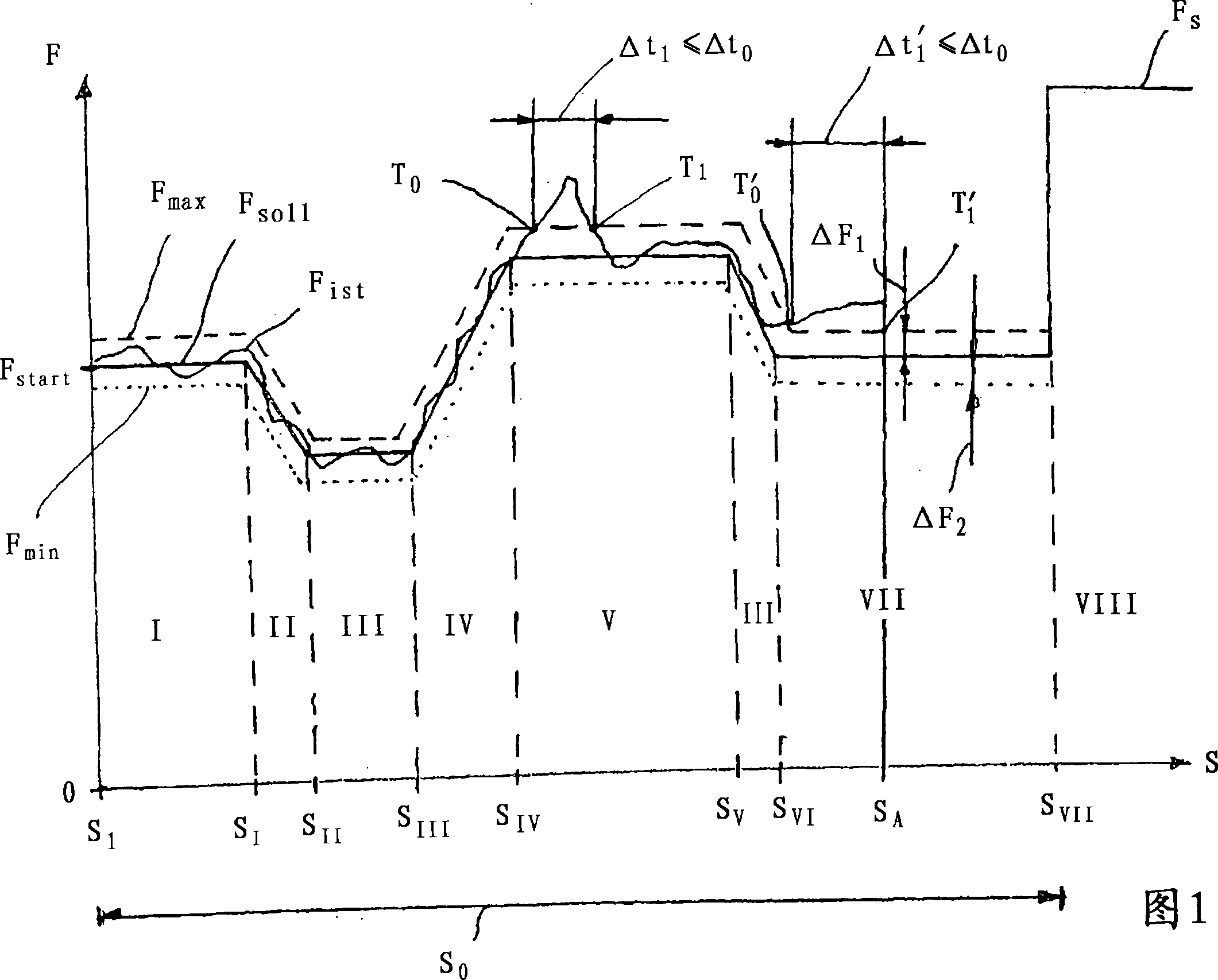
[0013] Figure 1 schematically shows the closing stroke S along the mold halves 0 force curve. Close stroke S 0 For example, it is divided into regions I to VII according to FIG. 1 . For example, a solid line consisting of straight line segments indicates the rated closing force F soll or the rated closing force along the closing stroke S 0 extension direction.

[0014] Especially with respect to the rated force F soll The dotted line offset parallel to the solid line indicates the maximum permissible closing force F max . Maximum allowable force F max The extension of the dotted line goes towards the rated closing force F soll The line of is deviated upward by an amount ΔF. Use S for the stroke point at the end of each zone I-VII I ~S VII express.

[0015] In zone I, rated closing force F soll For example with value F start . Nominal closing force F in zone II soll eg linearly down to a lower value. In zone III, rated closing force F soll Constantly held at t...


PUM


Abstract

The invention relates to a method for operating an injection moulding machine. A force Factual is measured during an opening and / or closing movement of a tool half along a path S0, and the force Factual is compared to a maximum permissible force Fmax and / or a minimal permissible force Fmin. A time measurement starts when the force Fmax is exceeded and / or when the force Fmin is not met. A drive of the tool half is switched off when the exceeded force Fmax and / or when the force Fmin which falls short exceeds a predetermined duration of time t0.

Description

technical field [0001] The invention relates to a method for operating an injection molding machine according to the preamble of claim 1 , in particular a method for triggering a mold safety device. Background technique [0002] From EP 1318005 A1 a method for triggering a mold safety device is known, in which the movement of a mold half is monitored along the travel path of a mold half. If it can be ascertained that there is no or only minimal movement of the components, the drive of the mold halves is switched off. The method relates to a stroke-based triggering method for the mold safety device, that is to say a drive that cuts off the mold halves if the displacement stroke per unit of time is exceeded. This method has been proven. However, in complex mold structures, such as injection molding molds with a large number of slides that have to be fed during the closing movement of the mold, the method does not always result in the desired accuracy. False triggering can o...

Claims


Application Information

Patent Timeline
Patent Type & Authority Applications(China)
IPC IPC(8): B29C45/16
CPCB29C45/76B29C45/844
Inventor G·格林
Owner KRAUSSMAFFEI TECH GMBH
Features
  • R&D
  • Intellectual Property
  • Life Sciences
  • Materials
  • Tech Scout
  • Unparalleled Data Quality
  • Higher Quality Content
  • 60% Fewer Hallucinations
Learn More