Support flange disassembling tool and support flange disassembling method

A technology for dismantling tools and flanges, which is applied in the direction of manufacturing tools, hand-held tools, chucks, etc., can solve the problems that the support flange cannot be removed, and achieve the effect of improving the efficiency of cutting operations

Active Publication Date: 2009-10-28
DISCO CORP
View PDF1 Cites 5 Cited by
  • Summary
  • Abstract
  • Description
  • Claims
  • Application Information

AI Technical Summary

Problems solved by technology

[0006] Since the support flange rotates together with the cutting tool at a high speed such as 40,000rpm or 60,000rpm, the inner diameter of the support flange expands due to centrifugal force, and the support flange moves toward the inside of the tapered spindle tip. , there is the following problem: a strong bite occurs between the support flange and the main shaft, and the support flange cannot be removed from the main shaft
In such cases, the support flange needs to be removed from the spindle frequently, accompanied by wear and tear of the cutting tool

Method used


Image

  • Support flange disassembling tool and support flange disassembling method
  • Support flange disassembling tool and support flange disassembling method
  • Support flange disassembling tool and support flange disassembling method

Examples


Embodiment Construction

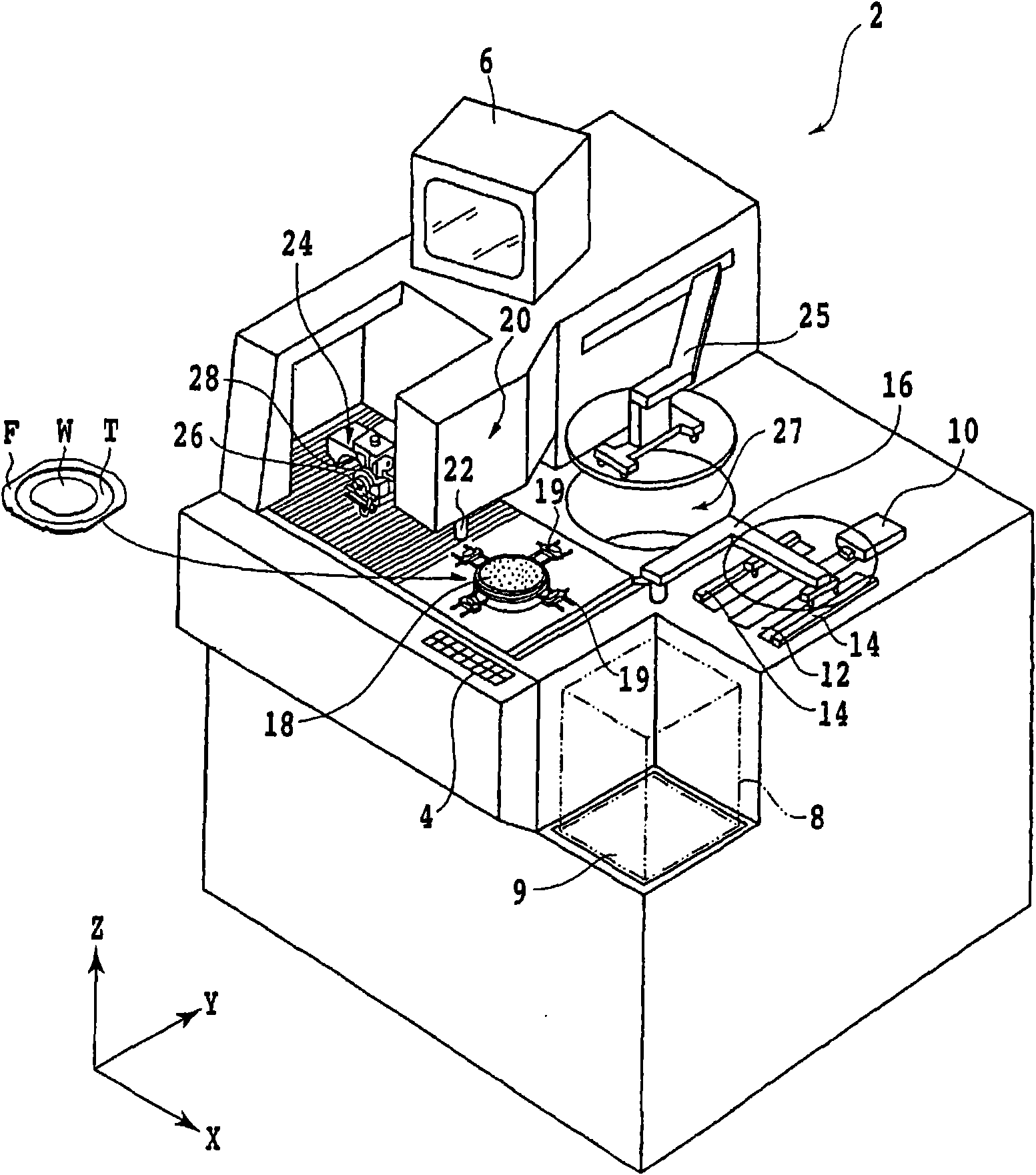
[0031] Hereinafter, embodiments of the present invention will be described in detail with reference to the drawings. figure 1 The appearance of the cutting device 2 according to the embodiment of the present invention that can cut a semiconductor wafer and divide it into individual chips (devices) is shown.

[0032] On the front surface side of the cutting device 2 is provided an operating member 4 for an operator to input instructions to the device such as machining conditions. A display unit 6 such as a CRT is provided on the upper part of the device, and the display unit 6 displays a guidance screen for an operator and an image captured by an imaging unit described later.

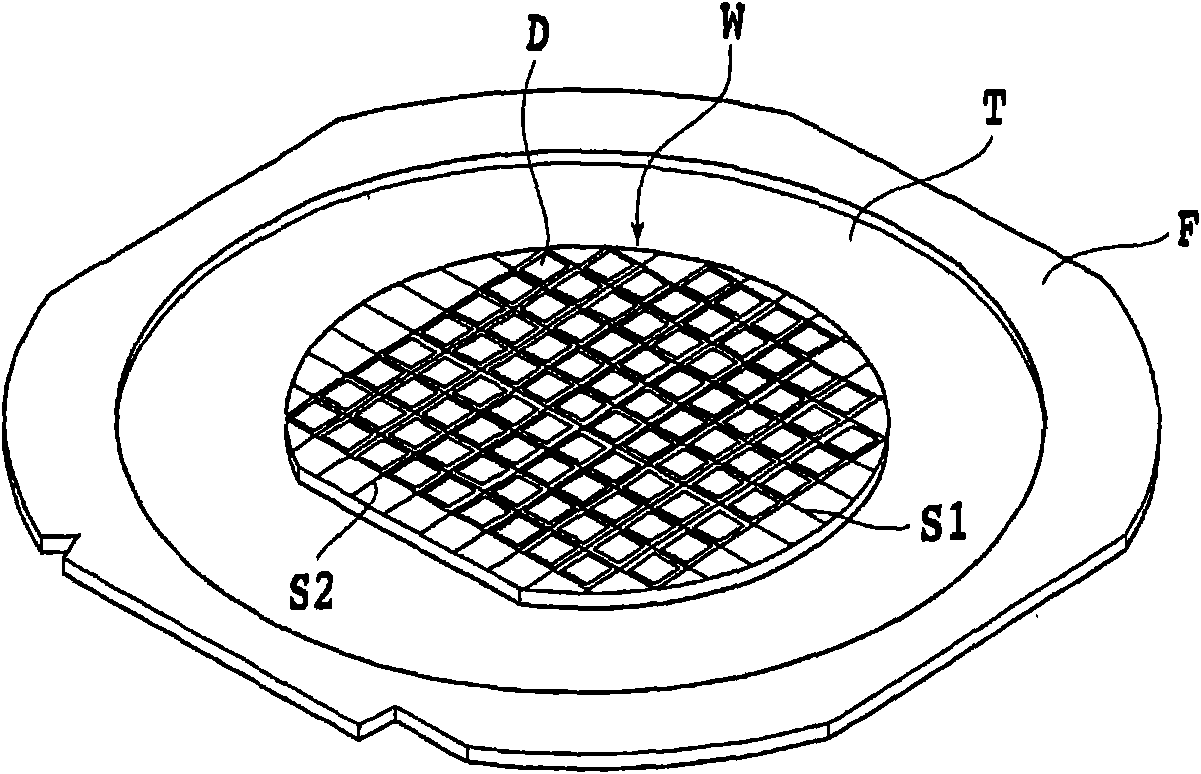
[0033] Such as figure 2 As shown, on the surface of the wafer W as the object of cutting, first and second separation streets S1 and S2 are formed orthogonally, and a plurality of devices D are divided by the first and second separation streets S1 and S2. formed on the wafer W.

[0034] The wafer W i...


PUM


Abstract

The invention provides a support flange disassembling tool and a support flange disassembling method. Wherein, the support flange disassembling tool can easily disassemble a support flange tightly engaged with the main shaft, is used for disassembling a support flange firmly which is assembled on the conical part of the main shaft which has a central blind hole and the conical part on the front end. The support flange disassembling tool is characterized in comprising: a tubular main body having a first thread hole penetrating the center, and a second thread hole on one end matching the external thread formed on the boss part of the support flange; and an opener having a handle part on one end, and a threaded rod on the other end; the threaded rod is longer than the handle part and the tubular main body, and can be screwed into the first thread hole of the tubular main body.

Description

technical field [0001] The present invention relates to a stand flange removal tool and a stand flange removal method for removing a stand flange for holding a cutting tool mounted on a main shaft of a cutting device from the main shaft. Background technique [0002] A cutting device for dividing a semiconductor wafer into individual devices includes: a chuck table that holds the wafer; and a cutting member that rotatably supports a cutting tool that is rotatable against the wafer held on the chuck table. Cutting is performed on the planned dividing line, and the cutting device can divide the wafer into individual devices with high precision. [0003] The cutting member has: a main shaft unit, which drives the main shaft to rotate; a support flange, which is mounted on the front end of the main shaft; a cutting tool, which is mounted on the support flange and has a thin cutting edge; and a fixing nut, which holds the The cutting tool is fixed on the support flange. [0004...

Claims


Application Information

Patent Timeline
Patent Type & Authority Applications(China)
IPC IPC(8): B25B27/02B23B31/02
Inventor 福冈武臣广沢俊一郎
Owner DISCO CORP
Why Eureka
Try Eureka