Seal cover

A technology for sealing caps and mechanical parts, applied in the field of metal sealing caps, can solve problems such as damage to the inner peripheral surface of outer ring components, and achieve the effect of effective fitting force and inhibition of detachment

Inactive Publication Date: 2011-08-10
UCHIYAMA MFG
View PDF9 Cites 5 Cited by
  • Summary
  • Abstract
  • Description
  • Claims
  • Application Information

AI Technical Summary

Problems solved by technology

However, in this case, the inner peripheral surface of the outer ring member is also damaged due to the compression deformation of the large-diameter portion when the cover member is attached, which is also not preferable.

Method used


Image

  • Seal cover
  • Seal cover
  • Seal cover

Examples


Embodiment Construction

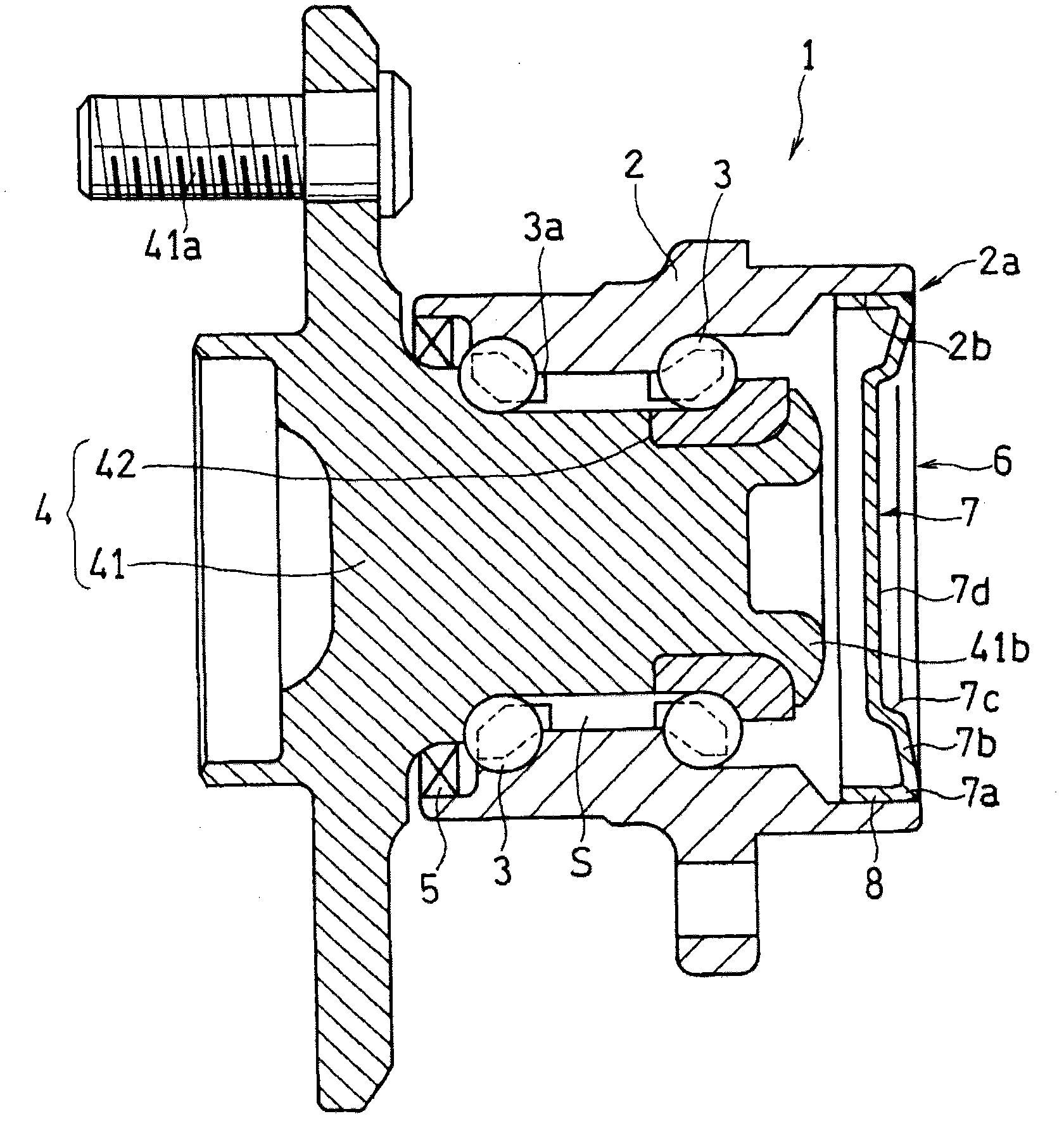
[0024] Embodiments of the present invention will be described below based on the drawings. figure 1 Indicates a bearing device that rotatably supports the driven wheels of an automobile. In the bearing device 1 shown in the illustration, a hub 41 and an inner ring member 42 are axially rotatably supported on an outer ring member (cylindrical mechanical member) fixed to a vehicle body (not shown) via two rows of rolling elements (balls) 3 . . . )2 on the inner diameter part. A driven wheel (rim) not shown is attached to the hub 41 with bolts 41 a. The inner ring 4 on the rotating side is constituted by the hub 41 and the inner ring member 42 . The rolling elements 3 are interposed between the outer ring member 2 and the inner ring 4 while being held by the cage 3 a. Between the wheel-side end portions of the outer ring member 2 and the inner ring 4 along the axial direction of the hub 41 , a shaft seal type seal ring (oil seal) 5 is attached while maintaining a mutual slidin...


PUM


Abstract

The invention provides a seal cover, which is disposed on an opening end of a cylinder-shaped mechanical component without damaging the opening end. Even when the inner pressure of the installed cylinder-shaped mechanical component increases, the seal cover will not be separated and can be maintained in a stable installing state. The seal cover (6) is made of metal and is used for sealing an inner cylinder part (2b) of the mechanical component (2a). The seal cover (6) is formed in a manner that a disc-shaped cover body (7) and the periphery part (7a) of the cover body (7) are connected through integration, and is pressed in from the opening end part (2a) of the cylinder-shaped mechanical part (2) and is imbedded in a cylinder part (8) in the inner cylinder part (2b) of the mechanical component (2a). The cover body (7) comprises a cone-shaped part (7b), where the inner diameter gradually reduces of the inner cylinder part (2b) facing towards the mechanical component (2a).

Description

technical field [0001] The present invention relates to a metal sealing cap that is installed on the opening end of a cylindrical mechanical part to close the inner cylinder of the mechanical part, and more specifically, relates to a method for rotatably supporting a driven wheel of an automobile, for example. The sealing cover is installed on the open end of the outer ring part of the rolling bearing device. Background technique [0002] As an example of the above-mentioned rolling bearing device that rotatably supports a driven wheel of an automobile, the rolling bearing device disclosed in Patent Document 1 can be cited. The rolling bearing device disclosed in Patent Document 1 includes: an outer ring member fixed to a vehicle body; an inner ring and a hub rotatably supported by the outer ring member through multiple rows of rolling elements; and a seal ring for sealing the bearing space. . The hub is inserted into the outer ring member from the outer side (outer side o...

Claims


Application Information

Patent Timeline
IPC IPC(8): F16J15/08F16C33/76
CPCF16C2326/02F16C19/186F16C33/723F16C33/768
Inventor 寺泽宽荒川贵信
Owner UCHIYAMA MFG
Why Eureka
Try Eureka