Novel spring set automatic positioning combined mechanism and positioning method thereof

A technology of automatic positioning and combination mechanism, which is used in positioning devices, metal processing mechanical parts, clamping and other directions, can solve the problems that the direction cannot be satisfied, cannot be guaranteed, cannot meet the positioning requirements, etc., achieve fast and accurate positioning, and ensure coaxiality. Effect

Active Publication Date: 2016-03-02
SHENYANG AIRCRAFT CORP
View PDF10 Cites 8 Cited by
  • Summary
  • Abstract
  • Description
  • Claims
  • Application Information

AI Technical Summary

Problems solved by technology

[0002] In the field of mechanical processing, there are often positioning methods that use tapered holes for positioning or require zero clearance between the cylindrical positioning holes on the product and the positioning pins. The use of tapered positioning pins is generally inserted from top to bottom, and the direction cannot meet the

Method used


Image

  • Novel spring set automatic positioning combined mechanism and positioning method thereof
  • Novel spring set automatic positioning combined mechanism and positioning method thereof
  • Novel spring set automatic positioning combined mechanism and positioning method thereof

Examples


Embodiment 1

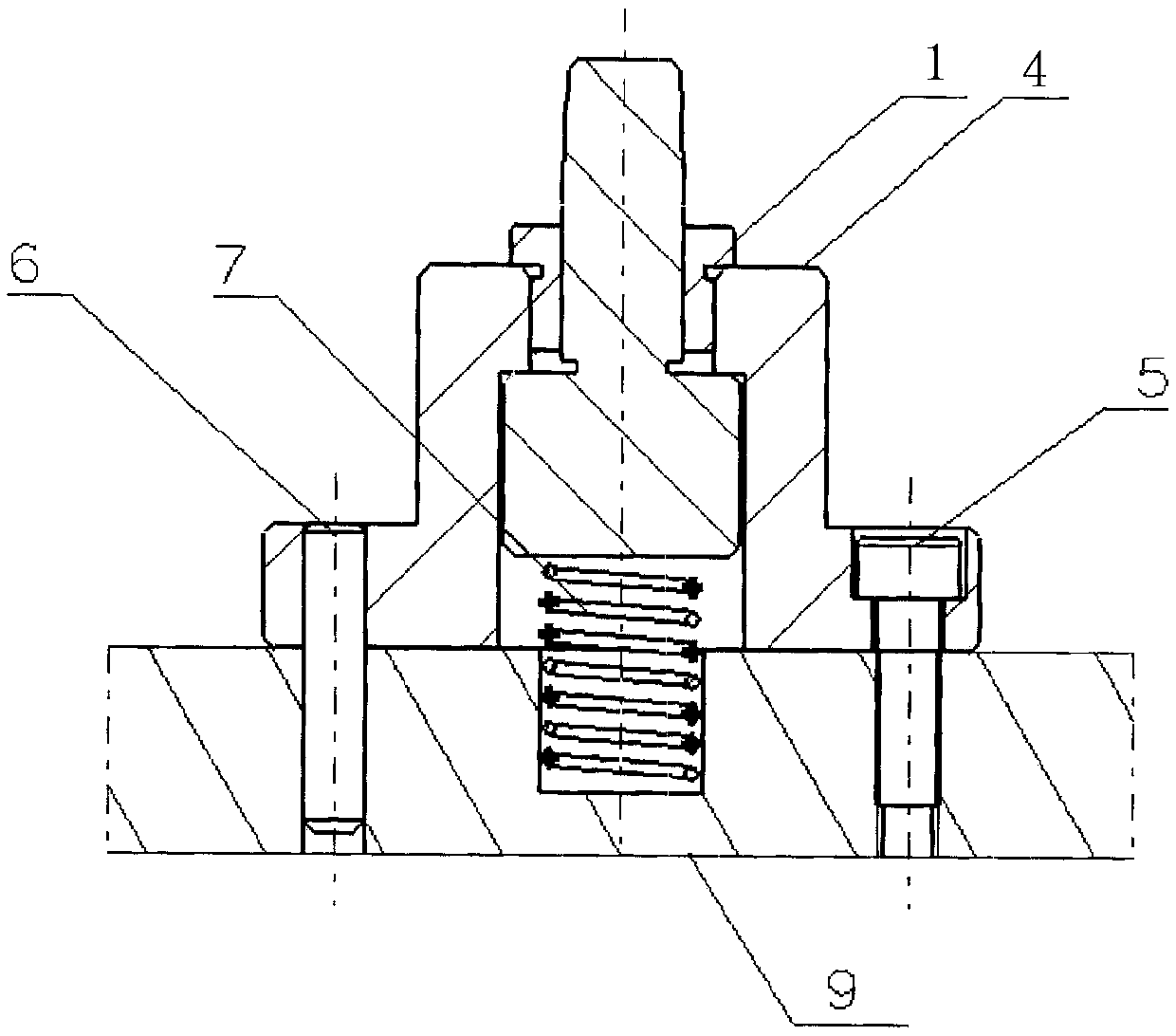
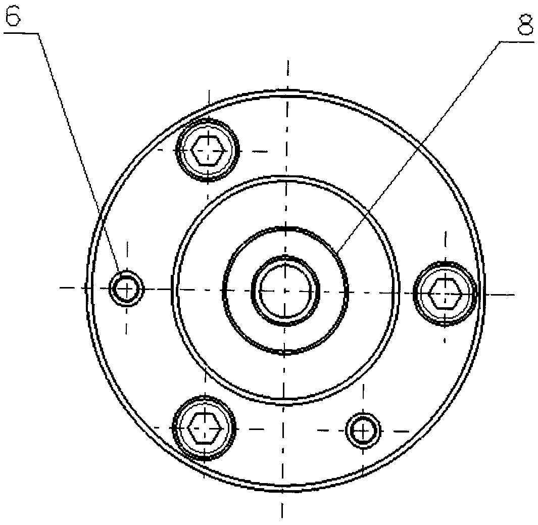
[0020] Such as figure 1 with figure 2 As shown, a new group spring automatic positioning combination mechanism is provided with a base 9 on the support surface of the clamp body, and the circular support 4 is positioned on the base 9 through two connecting cylindrical pins 6, and the circular support 4 It is connected with the base 9 through the screw 5; a cavity is provided in the circular support 4, a groove is provided at the position of the cavity corresponding to the base 9, a spring 7 is arranged in the groove, and the upper surface of the spring supports the conical column positioning pin 1 , the upper end of the conical column positioning pin 1 is a conical surface, and protrudes from the top of the circular support 4, and a bushing 2 is arranged between the conical surface of the conical column positioning pin 1 and the circular support 4, the lining The upper end of the sleeve 2 is provided with a boss, and is seated on the upper surface of the circular support 4, ...

Embodiment 2

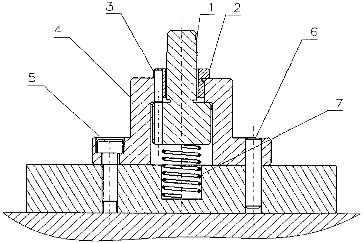
[0022] On the basis of the structure of Embodiment 1, the middle through hole of the bush 2 is processed into an oblong hole. It coincides with the axis of symmetry of the oblong hole in the length direction; the bottom of the circular support 4 is also provided with an oblong through groove, and the guide pins 3 are connected together in the two oblong through grooves 10 .

[0023] The method of positioning a part with two holes and one side by using a group of new group spring automatic positioning combination mechanism includes the following steps:

[0024] 1) Set the centers of the two bases 9 on the two positioning points specified by the technical requirements respectively, and install the circular support 4 and its internal spring 7 and conical column positioning pin 1 through the connecting cylindrical pin 6 and screw 5 , the positioning combination mechanism of one of the positioning points is the structure of embodiment one, and the positioning combination mechanism ...


PUM


Abstract

The invention relates to a novel spring set automatic positioning combined mechanism. A base is arranged on the supporting face of a clamp and used for positioning a round support through two cylindrical pins for connection. The round support is connected with the base through screws. A cavity is formed in the round support. A groove is formed in the position, corresponding to the cavity, of the base. A spring is arranged in the groove. The upper surface of the spring supports a conical-column-shaped positioning pin, and the upper end of the conical-column-shaped positioning pin is a conical face and extends out of the top end of the round support. A bush is arranged between the conical face of the conical-column-shaped positioning pin and the round support. A boss is arranged at the upper end of the bush, the bush is arranged on the upper surface of the round support, and the upper surface of the bush is a positioning face. The novel spring set automatic positioning combined mechanism is suitable for the automatic positioning and supporting of two holes and one face of a product to be machined, so that the reference face and the positioning face of the product are effectively attached, and quick so that installation and positioning of the product are achieved.

Description

technical field [0001] The invention relates to a novel group spring automatic positioning combination mechanism and a positioning method thereof, which are used to realize the positioning of two points and one side of a product, and can realize positioning processing of products with the same diameter of positioning holes and large tolerances. Background technique [0002] In the field of mechanical processing, there are often positioning methods that use tapered holes for positioning or require zero clearance between the cylindrical positioning holes on the product and the positioning pins. The use of tapered positioning pins is generally inserted from top to bottom, and the direction cannot meet the positioning needs. There is no guarantee that the fixed tapered locating pin can cooperate with the locating pin parts of the product locating hole, and the effective fit with the locating surface cannot be guaranteed. These two types of locating forms cannot meet the positioni...

Claims


Application Information

Patent Timeline
IPC IPC(8): B23Q3/18
CPCB23Q3/18
Inventor 王洪浩
Owner SHENYANG AIRCRAFT CORP
Why Eureka
Try Eureka