Pipe bending device of pipe bending machine applied for molding heat transferring tube of nuclear power evaporator

A nuclear power evaporator and pipe bending device technology, which is applied in the direction of feeding device, positioning device, storage device, etc., can solve the difficulty of ensuring parallelism and perpendicularity, it is difficult to ensure parallelism and perpendicularity, and it is impossible to locate both ends and other issues to achieve the effect of verticality guarantee

Active Publication Date: 2015-04-01
ZHANGJIAGANG DONGDA IND TECH RES INST
View PDF6 Cites 20 Cited by
  • Summary
  • Abstract
  • Description
  • Claims
  • Application Information

AI Technical Summary

Problems solved by technology

This common pipe bender can bend short steel pipes. The longer the steel pipe is, the more difficult it is to ensure parallelism and perpendicularity. It is obviously difficult for ordinary single-head pipe benders to guarantee parallelism and perpendicularity. , and for ordinary double-head pipe bending machines, since the two ends of the steel pipe cannot be positioned after the steel pipe is loaded, it cannot be guaranteed whether the two ends of the steel pipe are on the same axis between bending, so it is impossible to ensure parallelism degree and perpendicularity

Method used


Image

  • Pipe bending device of pipe bending machine applied for molding heat transferring tube of nuclear power evaporator
  • Pipe bending device of pipe bending machine applied for molding heat transferring tube of nuclear power evaporator

Examples


Embodiment Construction

[0016] The present invention will be described in further detail below through specific examples.

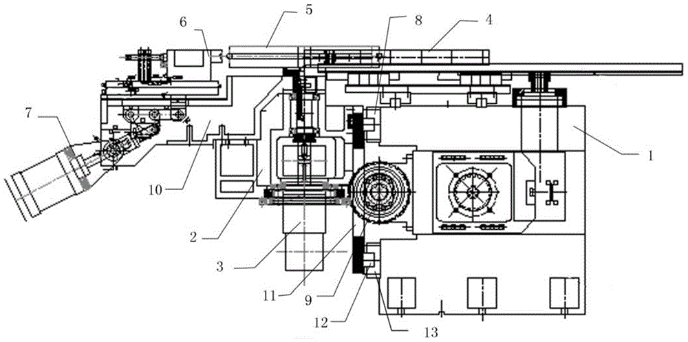
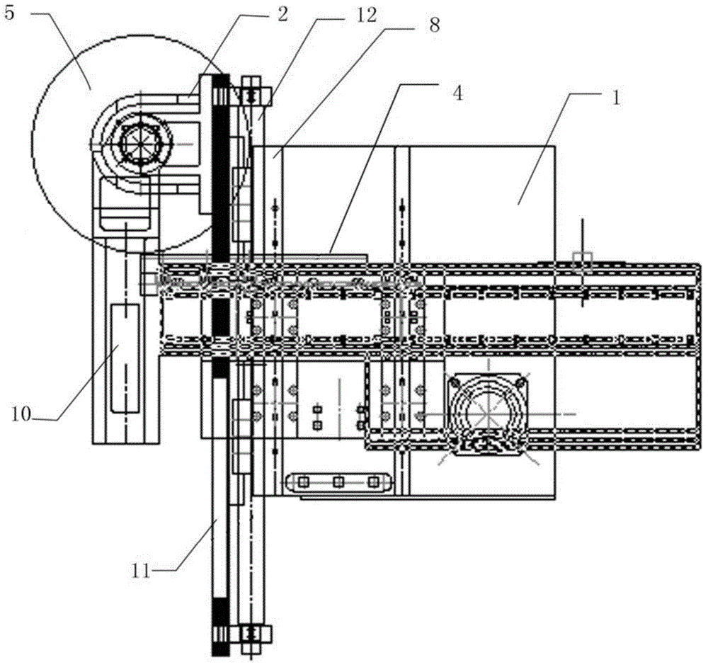
[0017] Such as figure 1 , 2 As shown, a pipe bending device of a pipe bending machine used for forming heat transfer tubes of nuclear power evaporators includes a machine head 1 and an auxiliary pushing device 4, and the auxiliary pushing device 4 is slidably installed on the On the machine head 1, the pipe bending device also includes a machine base 2 slidably installed on the machine head 1, the sliding direction of the machine base 2 is perpendicular to the axial direction of the steel pipe, and the machine base 2 is connected with the machine base driving device 9 ; the main shaft 3 installed on the machine base 2; the bending wheel mold 5 installed on the upper end of the main shaft 3; the pipe bending arm 10 installed on the machine base 2 is rotated, and the pipe bending arm 10 is driven by the arm driving device to rotate around the main shaft 3; The clamping device 6 ...


PUM


Abstract

The invention discloses a pipe bending device of pipe bending machine applied for molding heat transferring tube of nuclear power evaporator; the pipe bending device of pipe bending machine applied for molding heat transferring tube of nuclear power evaporator comprises a machine head, and an auxiliary pushing device; the auxiliary pushing device is slidably mounted on the machine head along the axial direction of the bending steel pipe; the pipe bending device further comprises a machine seat which is slidably mounted on the machine head; the sliding direction of the machine seat is perpendicular to the axial direction of the steel pipe; the machine seat is connected with a machine seat drive device; a main shaft is mounted on the machine seat; a bending die is mounted on the upper end of the main shaft; a pipe bending arm is rotatably mounted on the machine seat; an arm driving device drives the pipe bending arm to rotate around the main shaft; a clamping device is movably mounted on the pipe bending arm; and the clamping device clamps the steel pipe when bending the pipe. The pipe bending device uses the auxiliary pushing device to position the steel pipe, thus ensuring the levelness on two ends of the steel pipe; then uses the movable bending die to approach the auxiliary pushing device for achieving bending the pipe, thereby the parallelism and the perpendicularity of the bent steel pipe can meet the requirements.

Description

technical field [0001] The invention relates to a pipe bending device, in particular to a pipe bending device of a pipe bending machine used for forming heat transfer tubes of nuclear power evaporators. Background technique [0002] The heat transfer tube of the nuclear power evaporator is a U-shaped heat transfer tube. This kind of heat transfer tube needs to be bent with a tube as long as 10 meters. Due to the special environment used, the parallel sections on both sides of the U-shaped heat transfer tube The requirements for verticality and verticality between the pipes on both sides and the low section are relatively high, so the requirements for the quality of the bent pipe are very high. However, when the current common pipe bending machine bends the pipe, when the steel pipe enters the pipe bending station, the auxiliary pushing die moves to press the steel pipe, and then the pipe bending arm moves to bend the steel pipe into a specified angle. This common pipe bende...

Claims


Application Information

Patent Timeline
Patent Type & Authority Applications(China)
IPC IPC(8): B21D7/08B21D43/00
CPCB21D11/07B21D11/22
Inventor 魏平华余季华
Owner ZHANGJIAGANG DONGDA IND TECH RES INST
Why Eureka
Try Eureka