Electronic expansion valve

An electronic expansion valve and valve needle technology, which is used in lift valves, valve devices, lighting and heating equipment, etc., can solve the problem that electric valves have high requirements on the neutrality of valve needle components and nuts, and it is difficult to ensure the nut and valve needle wire. Rod assembly coaxiality, reducing the service life of the electronic expansion valve, etc., to avoid the valve port sealing is not tight, the coaxiality is high, and the installation is convenient.

Inactive Publication Date: 2015-01-14
ZHEJIANG DUNAN HETIAN METAL CO LTD
View PDF11 Cites 19 Cited by
  • Summary
  • Abstract
  • Description
  • Claims
  • Application Information

AI Technical Summary

Problems solved by technology

[0003] The invention patent with the publication number "CN102454818A" and the name "an electric valve" discloses an electronic expansion valve with the following structure: valve seat, valve core seat, valve needle screw assembly, nut, wherein the valve needle screw assembly is installed In the nut, and the nut and the valve core seat are set together. In fact, the electric valve with this structure has high requirements on the neutrality of the valve needle assembly and the nut. Since the nut and the valve core seat are processed separately, even if the nut and the valve core seat The valve core seat is set together, and it is difficult to ensure the coaxiality of the nut and the valve needle screw assembly, which makes the plastic nut easy to wear and reduces the service life of the electronic expansion valve

Method used


Image

  • Electronic expansion valve
  • Electronic expansion valve
  • Electronic expansion valve

Examples


Embodiment 1

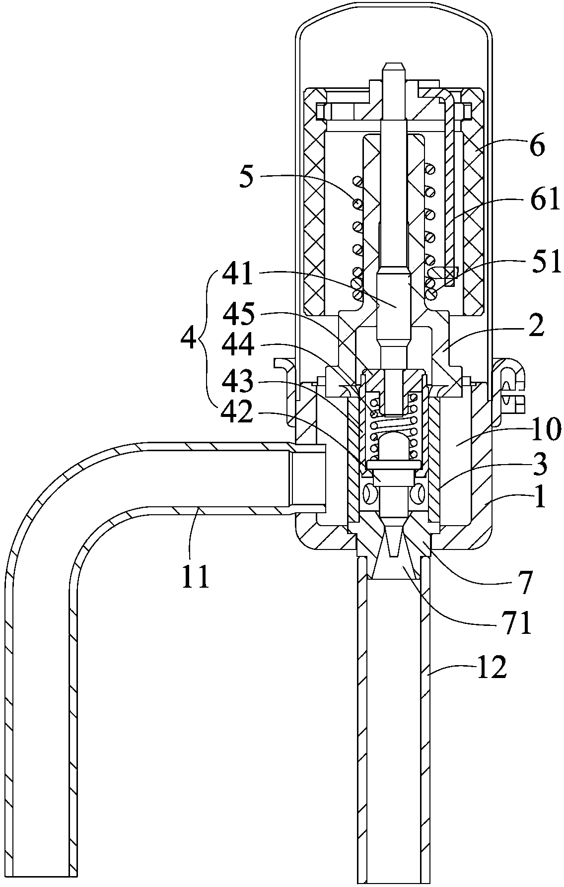
[0029] refer to figure 1 , 2 , the electronic expansion valve of this embodiment includes a valve body 1, a nut 2, a valve needle assembly 4, and a guide sleeve 3. The inside of the valve body 1 is a valve chamber 10, and the valve body 1 is connected with an inlet connecting pipe 11 and an outlet connecting pipe 12. The lower end of the valve body 1 is provided with a valve port seat 7, the valve port seat 7 is provided with a valve port 71, the valve port 71 corresponds to the outlet connecting pipe 12, the lower end of the guide sleeve 3 is socketed with the valve port seat 7; the valve needle assembly 4 includes a valve needle 42, The screw rod 41 and the positioning sleeve 43, the lower end of the screw rod 41 and the upper end of the positioning sleeve 43 are fixedly connected through the valve needle sleeve 45, the valve needle 42 is movably installed at the lower end of the positioning sleeve 43, and a valve needle is arranged between the valve needle 42 and the screw ...

Embodiment 2

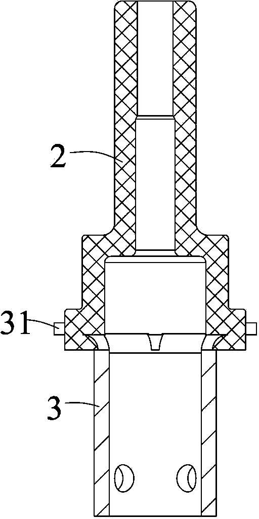
[0036] refer to Figure 4 , 5 , the structure of the electronic expansion valve in this embodiment is roughly the same as in Embodiment 1, the difference is that the connecting piece 31 and the guide sleeve 3 are separate structures, the connecting piece 31 is ring-shaped and fixed on the upper end of the guide sleeve 3, and the fixing method can be It is an interference fit or solder connection. The split structure of the connecting piece 31 can avoid the problem of deformation of the connecting piece 31 caused by the residual stress formed by the stamping and bending process, and the stability is better.

[0037] The connecting piece 31 is provided with an injection hole 33, which is convenient for the injection material to pass through during the injection molding process; the nut 2 or the connecting piece 31 is also provided with a spring guide rail positioning hole 34, so that the lower end of the spring guide rail is limited. For other structures of the electronic expa...

Embodiment 3

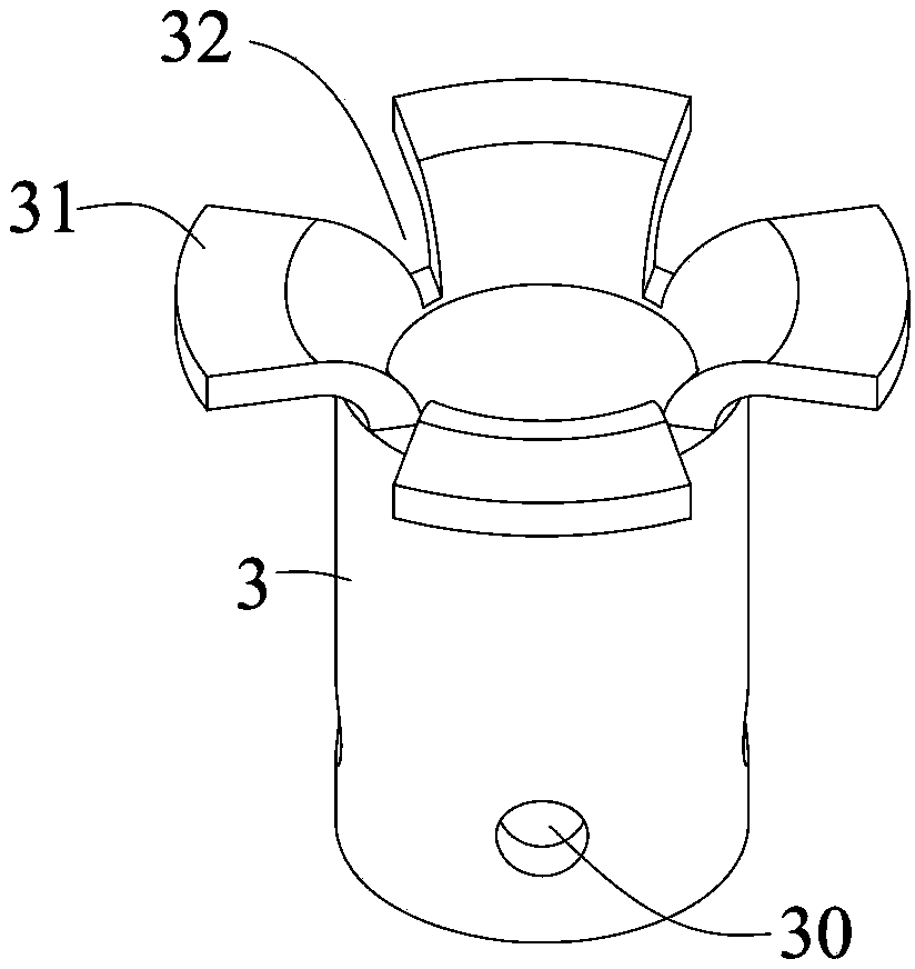
[0039] refer to Figure 6 , 7 , the structure of the electronic expansion valve in this embodiment is roughly the same as that in Embodiment 1, the difference is that the connecting piece 31 and the guide sleeve 3 are separate structures, and the connecting piece 31 is ring-shaped and can be axially slidably sleeved on the guide sleeve 3 upper end. During specific implementation, the upper end of the guide sleeve 3 forms a necking boss 35, and there is a clearance fit between the connecting piece 31 and the necking boss 35, and the connecting piece 31 can freely slide axially on the necking boss 35. During injection molding, The shrinkage boss 35 is inserted into the inner hole at the lower end of the nut 2, and the depth of the shrinkage boss 35 inserted into the nut 2 can be adjusted according to the installation requirements of the guide sleeve 3 in the inner cavity of the valve body 1, so as to better fix the guide sleeve 3 ; In addition to the above method, it is still ...


PUM


Abstract

The invention discloses an electronic expansion valve, belongs to the technical field of refrigeration system control, and solves the technical problem of wear caused by the coaxiality difference between the existing electronic expansion valve nut and a valve needle assembly. The electronic expansion valve comprises a valve body, a nut, a valve needle assembly and a guide sleeve, wherein the nut and the guide sleeve are assembled on the valve body, and the valve needle is arranged on the nut; the nut and the guide sleeve are integrally molded by injection.

Description

【Technical field】 [0001] The invention relates to an electronic expansion valve, in particular to an electronic expansion valve used in refrigeration systems such as air conditioners and refrigerators. 【Background technique】 [0002] The electronic expansion valve is an important part in the refrigeration system, which mainly plays the role of throttling and reducing pressure and regulating flow. The existing electronic expansion valve includes a valve body, a nut, and a valve needle assembly threadedly engaged with the nut. A driving device is used to drive the valve needle assembly to rotate while generating axial movement to adjust the opening of the valve port to achieve flow control. [0003] The invention patent with the publication number "CN102454818A" and the name "an electric valve" discloses an electronic expansion valve with the following structure: valve seat, valve core seat, valve needle screw assembly, nut, wherein the valve needle screw assembly is installed...

Claims


Application Information

Patent Timeline
Patent Type & Authority Applications(China)
IPC IPC(8): F16K1/32F16K1/38F25B41/06F25B41/34
CPCF16K1/32F25B41/34F25B41/31Y02B30/70
Inventor 王定军康志军刘正
Owner ZHEJIANG DUNAN HETIAN METAL CO LTD
Why Eureka
Try Eureka