
Combing machine

A combing machine and combing technology, applied in the field of combing machines, can solve the problems of intermittent acceleration of fiber sliver, material inversion, complex motion, etc.

Inactive Publication Date: 2007-07-04
MASCHINENFABRIK RIETER AG
View PDF3 Cites 9 Cited by
  • Summary
  • Abstract
  • Description
  • Claims
  • Application Information

AI Technical Summary

Problems solved by technology

[0005] The disadvantages of this device are: on the one hand, the complex movement of the lower joining roller, and on the other hand, the intermittent acceleration of the carrying out of the joining operation and the ejection of the transported fiber strands
In this case, there is similarly the risk that the material is reversed in the region of the delivery point of the conveyor belt when the fiber bundle hits the conveyor belt at high speed

Method used


Image

  • Combing machine
  • Combing machine
  • Combing machine

Examples


Embodiment Construction

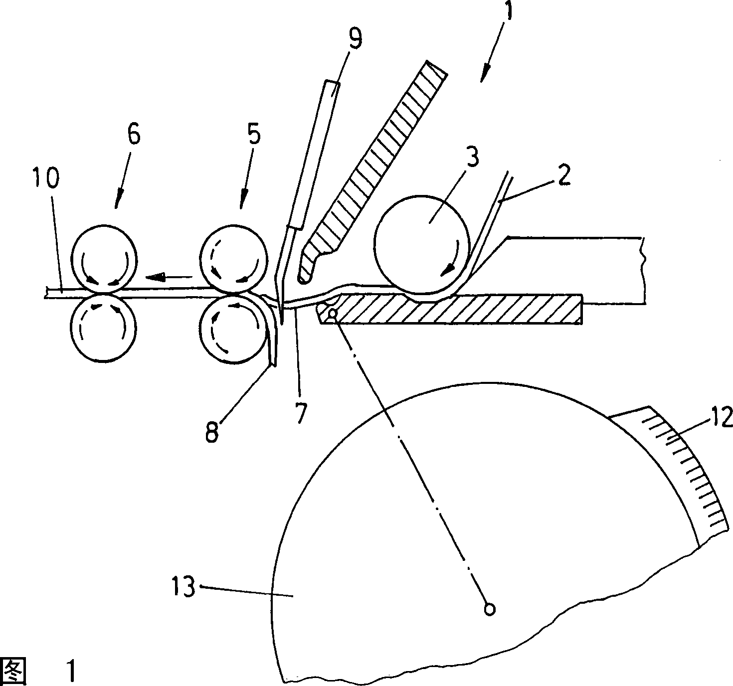
[0057] Figure 1 shows an embodiment according to the prior art, in which a lap sheet 2 supplied by a clamping assembly 1 is supplied via a supply cylinder 3 to a pair of take-off rollers 5 (also called detachment rollers). The fiber fringe 7 protruding from the open gripper 1 enters in this case on the carded fiber strip 10, so that the fiber fringe 7 enters the take-off roller 5 due to the forward movement of said take-off roller in the jaws of the In this case, fibers not held by the lap sheet or the retaining force of the gripper are torn out of the composite structure of the lap sheet. During this separating operation, the fiber ear is additionally drawn by the needles of the fixed comb 9 . The stationary comb 9 in this case causes to comb the rear part of the removed fiber ear and also retains neps, impurities etc. Because of the speed difference between the take-off speed of the lap sheet 2 and the detaching roller, the taken-off fiber ear is drafted to a certain lengt...


PUM


Abstract

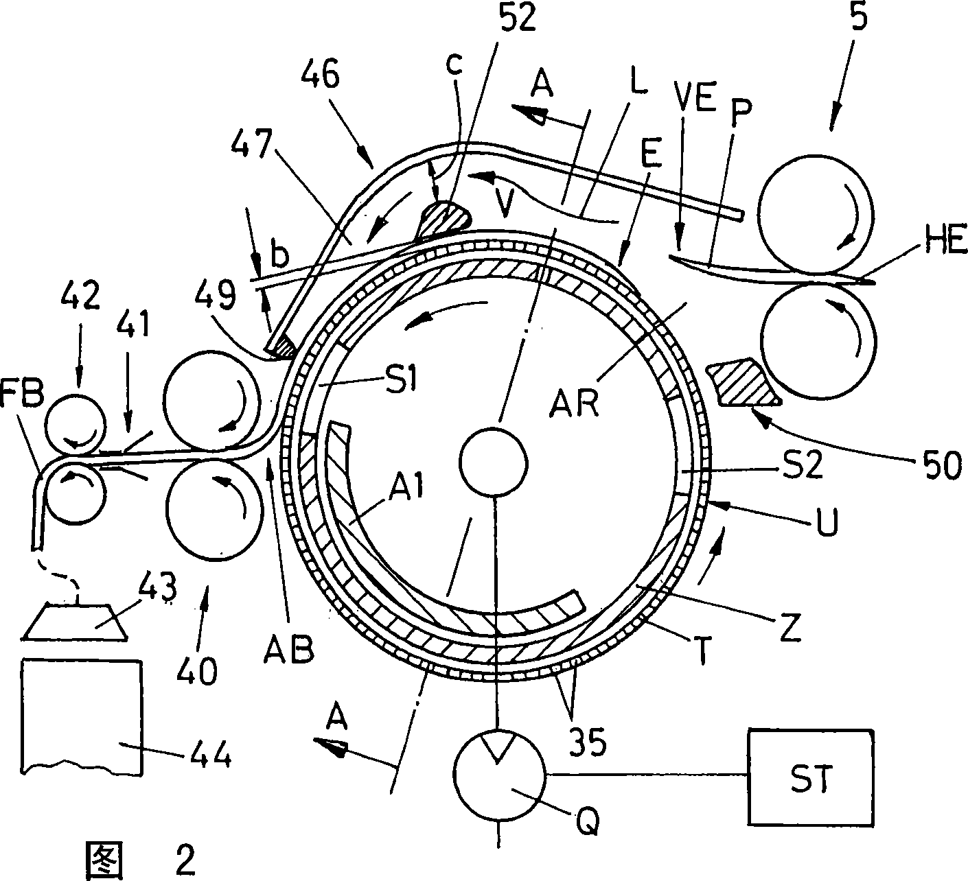
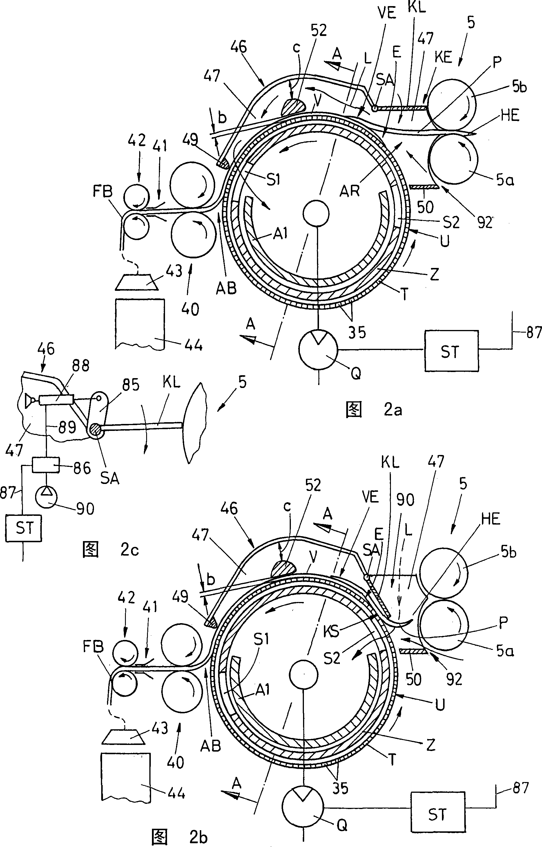
The invention relates to a combing machine with an assembly (1), for the introduction of a fibre mass (2) to a combing device (12, 13), whereby the combing device combs the end (7) of the fibre mass which is alternately let in and clamped by the assembly, which is subsequently introduced into a draw-off device (5) which draws off a fibre packet (P) from the combed end and supplies the same to a subsequent device (T, Z), for the formation of a fibre fleece (V). According to the invention, a reciprocating motion of the conventional draw-off devices (5) and a simplification of known solutions may be achieved, whereby the device (T, Z) comprises a circulating means (T), provided with openings (35) around the circumference on the periphery (U) thereof for an air inlet and at least one partial region of the interior of the circulating means (T) is connected to a vacuum source (Q) and provided with a casing (46, 47), forming a chamber (AR), isolated from the environment, between the draw-off device (5) and the periphery (U) of the circulating means (T), whereby a partial region of the isolated chamber (AR) is formed by the periphery (U) of the means (T) and by the draw-off device (5).

Description

technical field [0001] The invention relates to a combing machine with an assembly for supplying a fibrous body into a combing device which combs the end of said fibrous body which is gradually fed and gripped by the assembly and This is then fed to a take-off device which takes the fiber bundle from the fed and carded end and discharges it to a subsequent device which forms the fiber sliver. Background technique [0002] In known combing machines, the lap sheets removed from the lap are supplied via a nip device by supply rollers to circular combs arranged below the nip device so that they can be combed. During the combing operation, the gripping device swinging back and forth is closed, the lap end (also called fiber ear) protruding from the gripping wire of the gripping device is gripped by the carding zone of the circular comb and combed. The clamping device is then pivoted to the front position, simultaneously opening. In this case, the free end of the ear of fibers ...

Claims


Application Information

Patent Timeline
IPC IPC(8): D01G19/20D01G19/28
CPCD01G19/28D01G19/20
Inventor W·斯拉维克U·斯图茨D·索默
Owner MASCHINENFABRIK RIETER AG
Learn More