
Pressure-controlled navigating in a touch screen

A touch screen, touch position technology, applied in the input/output process of data processing, instruments, electrical digital data processing, etc., can solve the problem of not being able to access easily

Inactive Publication Date: 2007-07-04
KONINK PHILIPS ELECTRONICS NV
View PDF3 Cites 25 Cited by
  • Summary
  • Abstract
  • Description
  • Claims
  • Application Information

AI Technical Summary

Problems solved by technology

[0004] US Patent 6211856 relates to a Graphical User Interface (GUI), "touch screen" with a complete set of icons displayed at a scale where the individual function of each icon is identifiable, but too small to easily access the Features of function

Method used


Image

  • Pressure-controlled navigating in a touch screen
  • Pressure-controlled navigating in a touch screen
  • Pressure-controlled navigating in a touch screen

Examples


Embodiment Construction

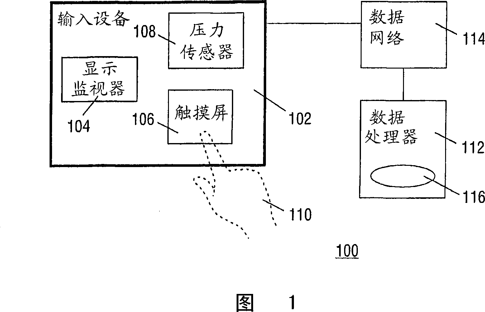
[0016] FIG. 1 is a block diagram of a system 100 of the present invention. System 100 includes a user input device 102 which itself has a display monitor 104 , a pressure sensitive touch screen 106 and a pressure sensor 108 . The touch screen 106 is mounted above the display monitor 104, but these entities are drawn here as separate components for clarity of the drawing. Sensor 108 detects the amount of pressure exerted by user 110 on screen 106 . The system 100 also includes a data processor 112 connected to the device 102, eg, via a data network 114, as shown. In another embodiment, device 102 and processor 112 are directly connected, eg, wirelessly or via a cable, or are integrated with each other in a single physical device, such as a cell phone or remote control device or the like. In this example, processor 112 includes control software 116 that causes system 100 to operate in accordance with the present invention.

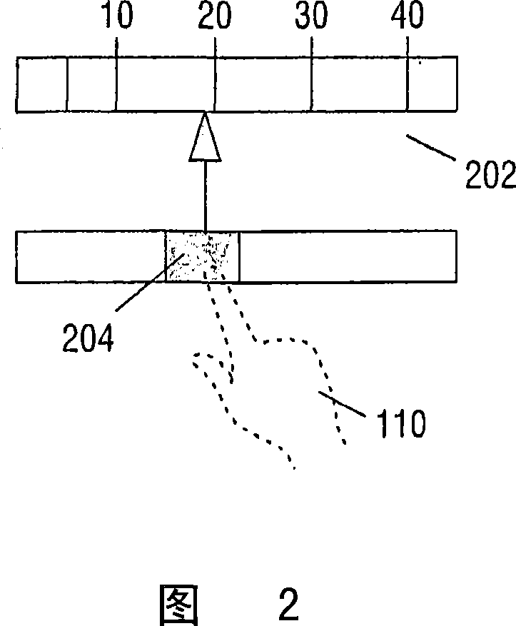
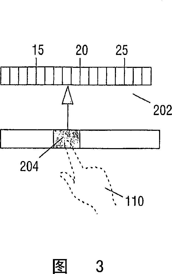
[0017] Figures 2 and 3 show a first application of ...


PUM


Abstract

A remote control device has a display monitor for rendering an image and a touch screen for user interaction. The touch screen is pressure-sensitive. The device has an operational mode wherein the image is being scaled dependent on a value of the pressure registered by the touch screen.

Description

technical field [0001] The present invention relates to a data processing system having a touch screen mounted on a display monitor for user interaction with the system. Background technique [0002] Examples of such systems are disclosed in documents such as US Patent 6466203 (Attorney Docket No. US000173) "HAND-HELD WITH AUTO-ZOOM FOR GRAPHICALDISPLAYOF WEB PAGE", and US Patent 6211856 (Attorney Docket No. PHA 23387) "GAPHICALUSER INTERFACE TOUCH SCREEN WITH AUTO-ZOOM FEATURE", both of which are hereby incorporated by reference in their entirety. [0003] US patent 6466203 relates to a mobile phone having a display monitor with a touch screen. The device has a browser and is capable of retrieving web pages from the Internet. The web page is displayed in full first. Users can recognize the general layout of the web page and the presence of hyperlinks. When the user touches a specific location on the touch screen corresponding to a portion of the web page image, that por...

Claims


Application Information

Patent Timeline
Patent Type & Authority Applications(China)
IPC IPC(8): G06F3/033G06F3/041G06F3/0488
CPCG06F3/0414G06F3/0488G06F2203/04806
Inventor R·E·F·范德芬G·J·德斯图拉M·希塞曼斯
Owner KONINK PHILIPS ELECTRONICS NV
Learn More