CMOS single stabilization circuit

A monostable circuit and circuit technology, applied in the direction of electrical components, electric pulse generation, pulse generation, etc., can solve the problems of low reliability, poor anti-interference ability, etc., to avoid direct impact, filter out the impact of interference signals, The effect of improving the anti-interference ability and reliability

Inactive Publication Date: 2007-07-11
BEIJING MXTRONICS CORP +1
View PDF0 Cites 5 Cited by
  • Summary
  • Abstract
  • Description
  • Claims
  • Application Information

AI Technical Summary

Problems solved by technology

Therefore, the existing monostable circuit has the disadvantages of poor anti-interference ability and low reliability.

Method used


Image

  • CMOS single stabilization circuit
  • CMOS single stabilization circuit

Examples


Embodiment Construction

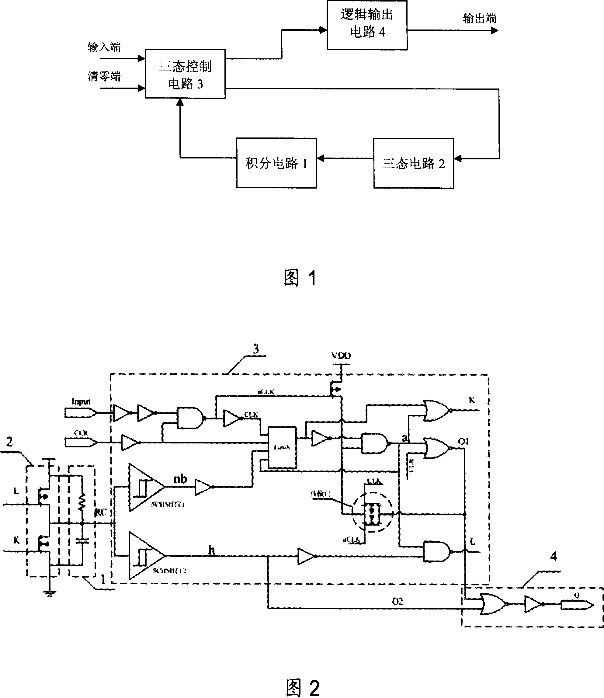
[0010] As shown in Figures 1 and 2, it is an overall circuit diagram of the present invention, that is, the basic form of the present invention. It is composed of an integrating circuit 1, a tri-state circuit 2, a control circuit 3 of a tri-state circuit and a logic output circuit 4. The monostable The state circuit has an input terminal Input, a clear terminal CLR and an output terminal. The control input of the three-state circuit 2 is generated by the three-state control circuit 3 , and the three-state control circuit 3 generates a control signal according to the state of the integrating circuit 1 . In addition, the three-state control circuit 3 uses two Schmitt triggers to sample the state of the integration circuit, and generates the control signal required by the three-state circuit 2 through logic operations according to the sampling results, and the logic output circuit 4 and the integration circuit 1 The state is related, but it is generated by the relevant signal in ...


PUM


Abstract

This invention relates to one CMOS signal stable circuit, which comprises integral circuit, three status circuit and its control circuit and logic output circuit, wherein, the control circuit generates control signals with input end, zero clear end and output end; the three status control circuit adopts two Smite trigger for sample on integral circuit to generate three status circuit needed control signals by sample result; the two Smite trigger generates output signals through logical computation.

Description

technical field [0001] The invention relates to a CMOS monostable circuit, which can be widely used in applications such as pulse shaping, time delay and timing. Background technique [0002] The salient feature of a monostable circuit is that it has two different working states: steady state and transient state. Under the action of an external trigger pulse, it can turn from a steady state to a temporary steady state, and after the temporary steady state is maintained for a period of time, it will automatically return to the steady state. The duration of the transient steady state depends on the parameters of the circuit itself, and has nothing to do with the amplitude of the trigger pulse. Generally speaking, a monostable circuit is composed of an integrating circuit, a tri-state gate and a tri-state gate control circuit. The output of the monostable circuit is directly determined by the result of the integral circuit, and the control signal of the tri-state gate control...

Claims


Application Information

Patent Timeline
Patent Type & Authority Applications(China)
IPC IPC(8): H03K3/013H03K3/033H03K3/355
Inventor 王晋乐立鹏赵宁蒋敏强
Owner BEIJING MXTRONICS CORP
Why Eureka
Try Eureka