

Droplet separator system
A droplet separator and separation technology, which can be applied in separation methods, dispersed particle separation, chemical instruments and methods, etc., can solve the problems of reducing the separation capacity of droplet separator devices.
- Summary
- Abstract
- Description
- Claims
- Application Information
AI Technical Summary
Problems solved by technology
Method used
Image

Examples
Embodiment Construction
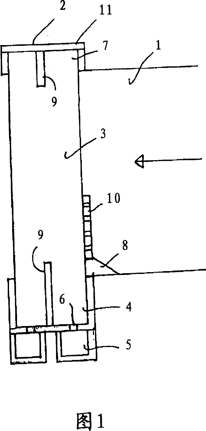
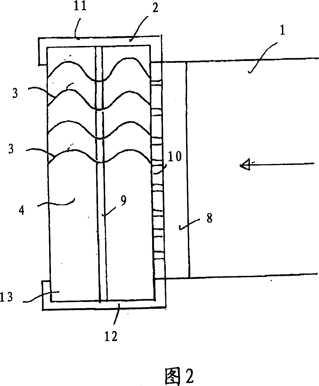
[0039] FIG. 1 shows a section of a flow channel 1 through which a liquid-laden gaseous medium flows. The direction of flow is indicated by the arrows shown. In order to separate the liquid present in the medium, the flow channel 1 leads into a dropper device 2 . The dropper device 2 comprises a frame 11 with two side walls 12 (shown in FIG. 2 ), an upper cover region 7 and a lower trough region 4 . The cover area 7 is located above the flow channel 1 and the groove area 4 is located below the flow channel. Inside the frame 11 are arranged a plurality of vertically arranged drop distributor profiles 3 parallel to one another, this being a laminated drop divider profile of known construction. These drop distributor profiles are not shown in great detail in the figures. Since they are known, no further details have to be stated in this respect. In any case, the flow deflection effected by the foil profile achieves separation of the droplets, which flow down the profile and co...
PUM
 Abstract
Description
Claims
Application Information